Heat dissipation device

a heat dissipation device and heat dissipation technology, applied in the direction of electrical apparatus construction details, basic electric elements, lighting and heating apparatus, etc., can solve the problems of poor overall thermal dissipation performance, and achieve the effect of rapid dissipation of thermal energy and improved thermal cycling performan

Inactive Publication Date: 2010-11-02
INVENTEC CORP
View PDF6 Cites 6 Cited by
  • Summary
  • Abstract
  • Description
  • Claims
  • Application Information

AI Technical Summary

Benefits of technology

[0012]In the present invention, through displacement, such as incline or swing, generated when operating the electronic device, the fluttering slices are actuated to swing, thus generating an airflow to disturb the air inside the electronic device and improve the thermal cycling performance, thereby rapidly dissipating the thermal energy generated by the electronic component.

Problems solved by technology

In view of the above problems, the present invention is to provide a heat dissipation device, which can solve the problem that a conventional heat dissipation device applied to a portable electronic device must be wired according to an internal circuit and cannot dissipate thermal energy by a fan, and thermal energy is merely dissipated in a natural convection mode through the contact of the surface of a heat sink and the air, thereby leading to poor overall thermal dissipation performance.

Method used


Image

  • Heat dissipation device
  • Heat dissipation device
  • Heat dissipation device

Examples


first embodiment

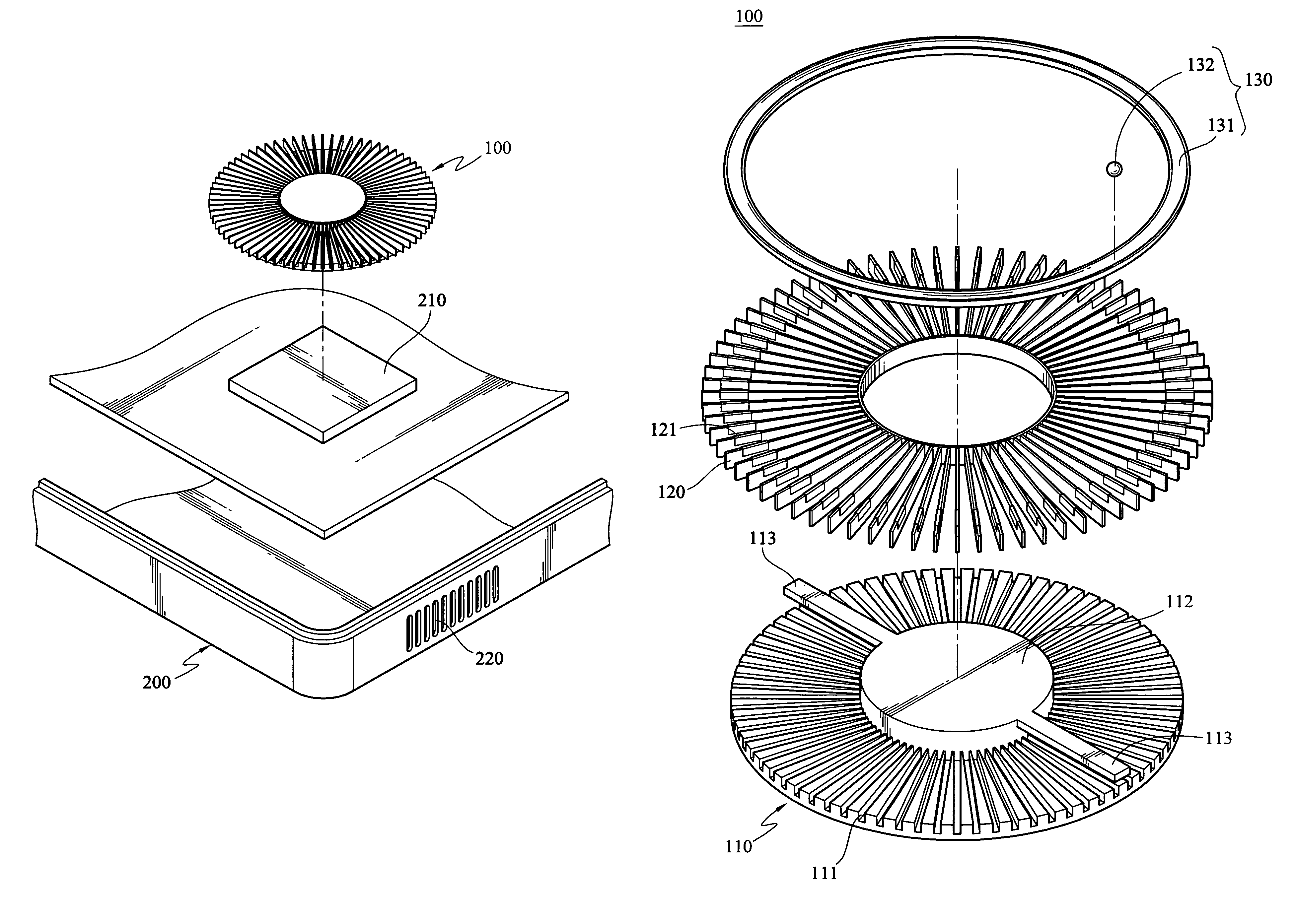
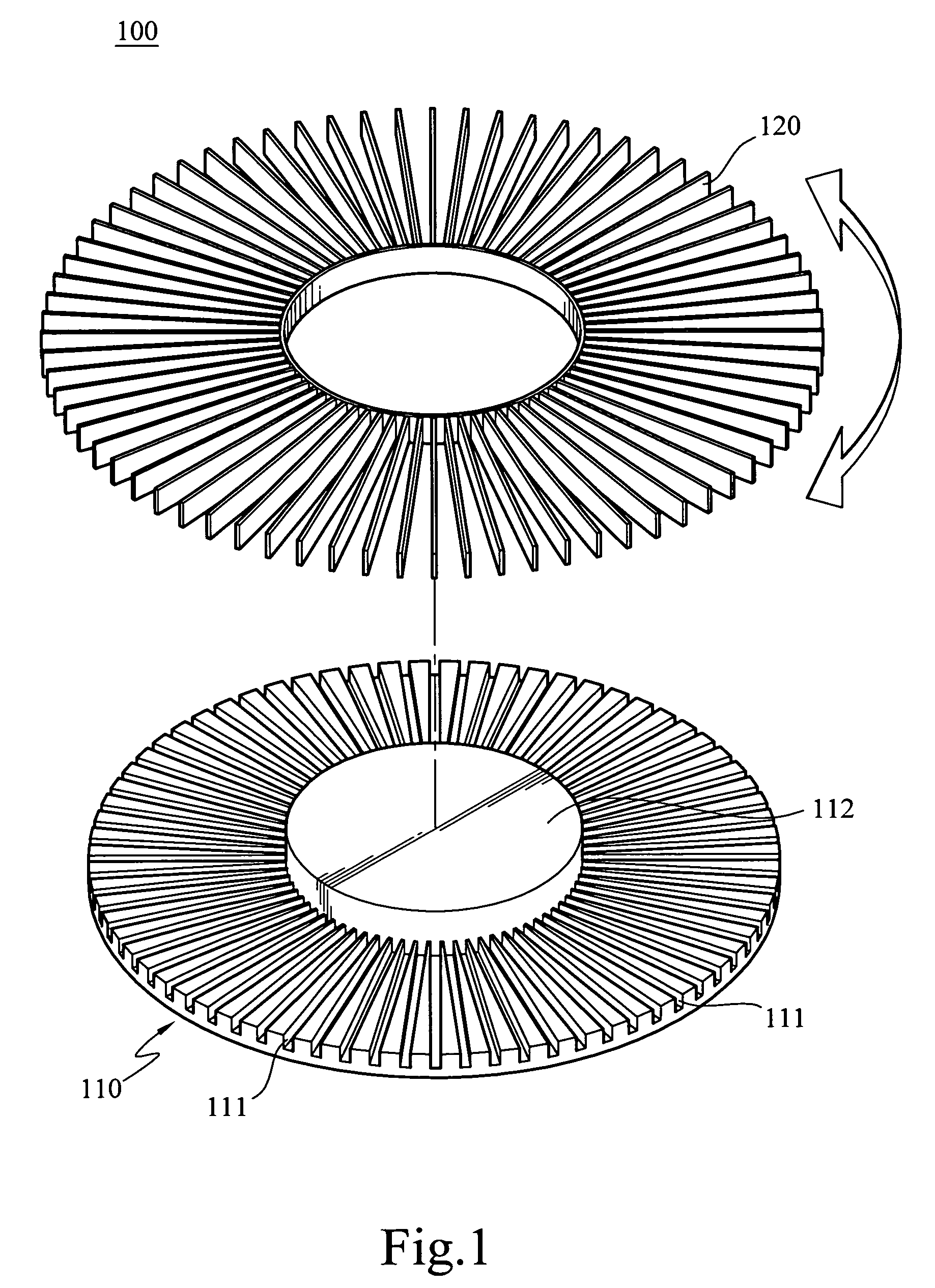
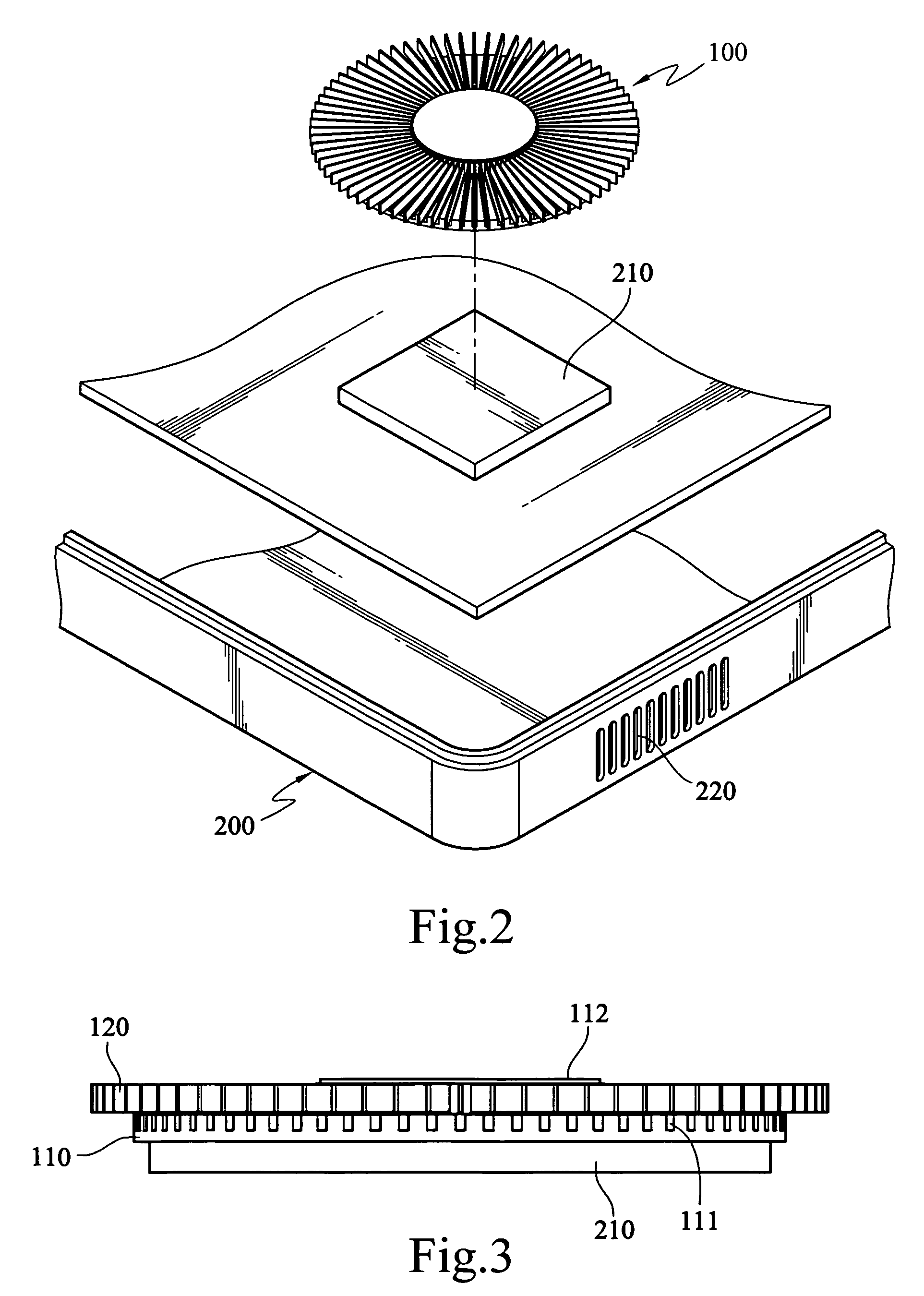
[0027]Referring to FIGS. 1 to 3, the present invention is shown. A heat dissipation device 100 of the present invention is disposed in an electronic device 200 to perform thermal exchange with an electronic component 210 in the electronic device 200. The electronic component 210 can be an electronic part or component that generates large thermal energy during operation, such as a chip and a CPU.

[0028]The heat dissipation device 100 of the first embodiment of the present invention includes a heat sink 110 and a plurality of fluttering slices 120. The heat sink 110 is of a disc structure. One side of the heat sink 110 is attached on the electronic component 210 to conduct the thermal energy generated by the electronic component 210. A plurality of grooves 111 is opened at the other side of the heat sink 110, and a cylindrical combination block 112 is protruded at the center. The fluttering slices 120 are made of a metal sheet or a flexible material, such that the fluttering slices 120...

fourth embodiment

[0034]FIGS. 8 and 9 show schematic views of the present invention. In addition to the circular structure disclosed in the previous embodiments, the heat sink 100 of the present invention can further be designed to have a square structure according to actual thermal dissipation requirement. The plurality of fluttering slices 120 is arranged on the heat sink 110 at a certain interval. Two tracks 131 are respectively disposed on the fluttering slices 120 in a direction perpendicular to the arrangement direction of the fluttering slices 120. Each fluttering slice 120 has a magnetic material 121 disposed at a position corresponding to the track 131. The ball 132 made of a magnetic material assists actuating the fluttering slices 120 to swing by the magnetic force.

[0035]According to the present invention, the arrangement position and the number of the track 131 can be changed correspondingly according to the thermal dissipation requirements of different types of electronic device 200. FIG...


PUM


Abstract

A heat dissipation device is disposed in an electronic device and performs thermal exchange with an electronic component of the electronic device. The heat dissipation device includes a heat sink and a plurality of fluttering slices. The heat sink is attached on the electronic component to conduct the thermal energy of the electronic component. The fluttering slices are disposed on the heat sink, and the fluttering slices are actuated to generate an airflow when the electronic device is moved, so as to disturb the air inside the electronic device, thereby achieving the purpose of improving the thermal dissipation performance.

Description

BACKGROUND OF THE INVENTION[0001]1. Field of Invention[0002]The present invention relates to a heat dissipation device, and more particularly to a heat dissipation device applied to a portable electronic device.[0003]2. Related Art[0004]Currently, with the rapid development of electronic technology, and more attention of consumers on the features of being light, thin and mobile of consumer electronic products, today's electronic products, for example, portable electronic devices such as notebooks, ultra mobile personal computers (UMPCs) and PDAs, are developed towards miniaturization gradually. As for users that often need to go outside, the portable electronic products become easier to carry, thus the convenience in use is improved significantly.[0005]As the operation speed of electronic components inside a computer device is accelerated, and the volumes of the electronic components are micro, the thermal energy produced per unit area is increased accordingly. If the thermal energy...

Claims


Application Information

Patent Timeline
Patent Type & Authority Patents(United States)
IPC IPC(8): H01L23/34F28F7/00
CPCH01L23/467F28F1/30H01L2924/0002H01L2924/00
Inventor WANG, FENG-KUWANG, SHAW-FUUHUANG, TING-CHIANGSYU, SHENG-JIE
Owner INVENTEC CORP
Why Eureka
Try Eureka