
Sealing element

Active Publication Date: 2010-11-09
ARZNEIMITTEL GMBH APOTHEKER VETTER & CO
View PDF28 Cites 17 Cited by
  • Summary
  • Abstract
  • Description
  • Claims
  • Application Information

AI Technical Summary

Benefits of technology

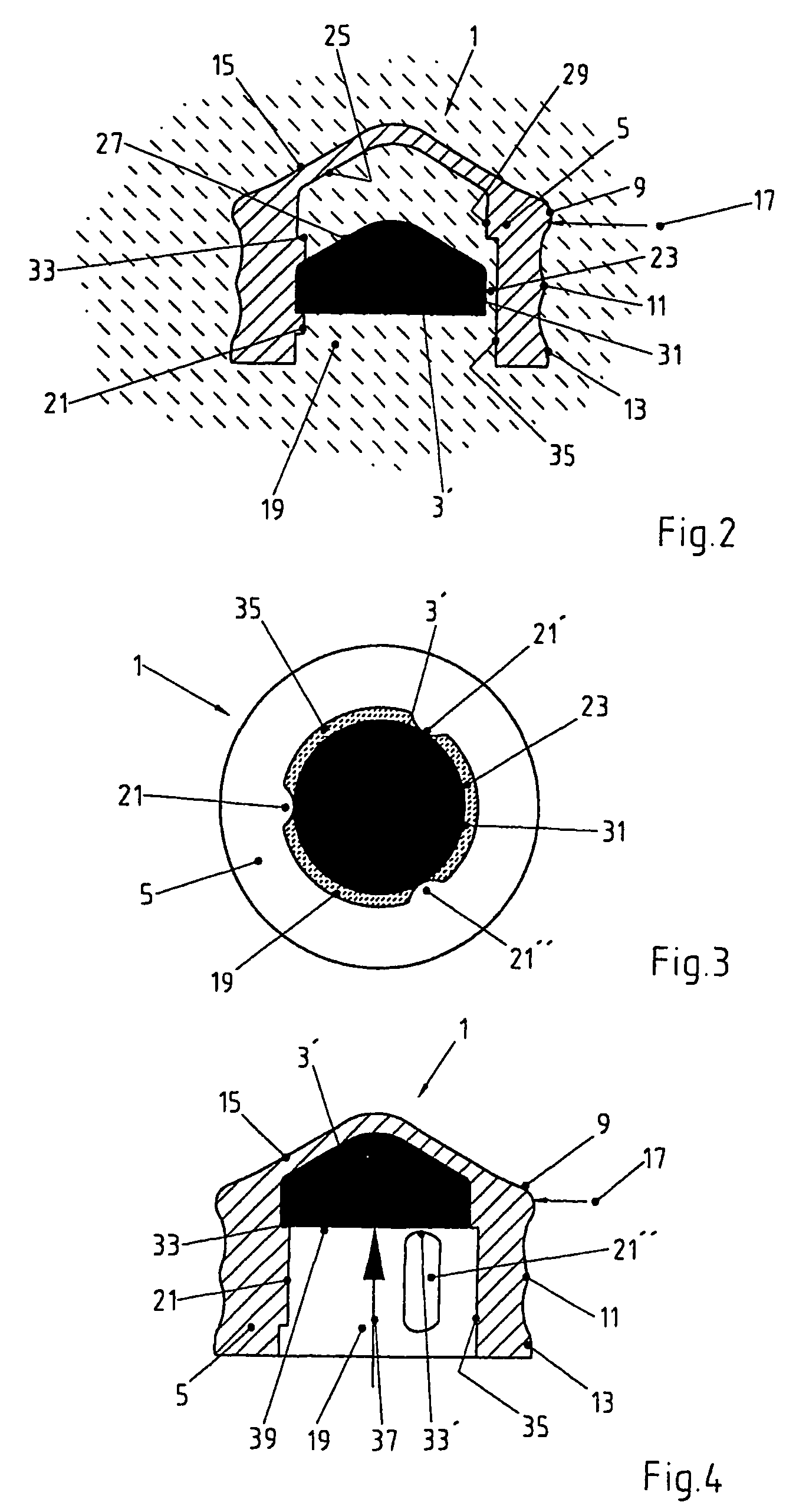
[0009]Another preferred embodiment example is characterized in that the sterilizing medium is guided into the inside of the sterilization element, i.e., that the channels run through this element. The sealing element is thus characterized by a simple structure.
[0010]Another preferred embodiment example is characterized in that the sterilization element is designed as a clamping element. In this way it is possible to optimally sterilize the sealing element and on the other hand, to ensure that with a simple structure a clamping of the sealing element, e.g., on a syringe body, is possible in a simple way.
[0012]An especially preferred embodiment of the sealing element is characterized in that the sterilization element forms a supporting element. It increases the mechanical strength of the sealing element in such a way that it can be used in connection with application aids, e.g., with motor-driven infusion and / or injection pumps without there being any malfunctions because the sealing element has elasticity that is too high.
[0014]To achieve the object of the invention, a method is also suggested for producing an injection system with a sealing element that has the characteristics named in claim 21 and is characterized in that the sealing element is preassembled first. This means, the parts of the sealing element are brought into the initial position, in which the later contact surfaces of the sealing element are still accessible to a sterilizing medium. In a next step, the sterilization is carried out. Finally, the parts of the sealing element are moved into their final positions in a final assembly step. The contact surfaces that are now formed are effectively cleaned in the preceding sterilization step, so that no contamination can result.

Problems solved by technology

It has been found that sealing elements of the type addressed here cannot be optimally sterilized in all cases: there are areas that cannot be reached directly by the sterilizing medium in a sterilizing method, e.g., during autoclaving, so that proper sterilizing cannot be ensured.

Method used


Image

  • Sealing element
  • Sealing element
  • Sealing element

Examples


Embodiment Construction

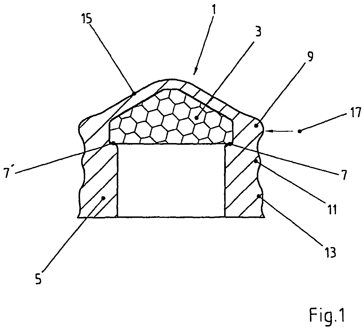
[0027]FIG. 1 shows a sealing element 1 that consists of a support element 3 with a stable shape and an elastically deformable sealing sleeve 5. The support element 3 and the sealing sleeve 5 are designed as cylindrical rotation elements. The sealing sleeve 5 is designed in such a way that it is in contact with the majority of the surface of support element 3, i.e., at least partially surrounds it. The sealing sleeve 5 has, on the inside, a surrounding step 7, 7′ that is also in contact with support element 3. Because of the elasticity of the sealing sleeve 5 and the step 7, into which the support element 3 can engage, the support element 3 is held securely.

[0028]Support element 3 is also characterized in that it has higher strength than the sealing sleeve 5. Thus it is used to stabilize the sealing element 1, in particular in the sense that the total elasticity of sealing element 1 is reduced, i.e., it is less compressible. Preferably the support element 3 is designed in such a way ...


PUM


Abstract

A sealing element is suggested, in particular one for closing primary packaging for medications, that has at least two parts, which touch each other at least in some areas. This is characterized in that steam-permeable channels are provided for sterilization of the contact surfaces. In addition, a method is suggested for manufacturing a syringe system with a sealing element. This is characterized by the steps—preliminary assembly of the sealing element, —sterilization of the sealing element, —final assembly of the sealing element.

Description

BACKGROUND[0001]1. Related Applications[0002]The present application is the U.S. National Phase of PCT Application PCT / EP02 / 05505, filed May 18, 2002, claiming priority to German Patent Application No. 10127779.2, filed Jun. 1, 2001.[0003]2. State of the Art[0004]The invention relates to a sealing element according to the preamble of claim 1 and a method for producing a sealing element according to the preamble of claim 21.[0005]Sealing elements and methods of the type addressed here are known. The sealing elements are used as sealing stoppers for primary packaging, as it is called, for medical purposes, especially for syringes and cannulas. It has been found that sealing elements of the type addressed here cannot be optimally sterilized in all cases: there are areas that cannot be reached directly by the sterilizing medium in a sterilizing method, e.g., during autoclaving, so that proper sterilizing cannot be ensured.[0006]Therefore it is the object of the invention to provide a se...

Claims


Application Information

Patent Timeline
IPC IPC(8): A61M5/32A61B19/00A61M39/00A61L2/07A61L2/18A61L2/20A61L2/26A61M5/142A61M5/158A61M5/31A61M5/315
CPCA61L2/07A61L2/18A61L2/20A61M5/31511A61L2/26A61M2005/3104A61L2202/121A61L2202/21
Inventor VETTER, UDO J.GLOCKER, JOACHIMSCHWARZ, WALTER
Owner ARZNEIMITTEL GMBH APOTHEKER VETTER & CO
Learn More