
Screw fastener in multiple floor truss and wood-to-wood shear connection

a screw and multiple floor technology, applied in the direction of screws, threaded fasteners, girders, etc., can solve the problems of long installation time, high labor intensity, and inability to accommodate the many nails that are required, so as to improve the load transfer rate, and install a few screws much faster

Inactive Publication Date: 2010-11-16
SIMPSON STRONG TIE
View PDF42 Cites 18 Cited by
  • Summary
  • Abstract
  • Description
  • Claims
  • Application Information

AI Technical Summary

Benefits of technology

[0018]An advantage of the present invention is that screws can connect the trusses before or after the trusses are “in place”.

Problems solved by technology

Moreover, some undesirable looseness is inherent in the connection by contractors who may inadvertently overdrill the bolt holes, or simply by the fact that wood shrinkage occurs after installation of the bolts.
The problem with holdowns which use nails is the fact that they must be very long to accommodate the many nails that are required.
Many contractors now use nailing guns to drive the nails, but for the person who does not have a nailing gun, the prospect of driving 23 nails for each strap holdown means the expenditure of a great deal of energy driving the nails.
The problem with screws, particularly for large loading in shear is that standard screws have several weaknesses.
First, it was found that the heavy duty power drivers snapped the heads off a high percentage of standard screws before the clutch disengaged the drive at the end of the driving cycle when the head abruptly reached the immovable sheet metal connector plate.
Second, those screws which had adequate unthreaded shank portions to resist the large shear loads, split the wood upon installation or shortly thereafter because the diameters of the unthreaded portions were larger than the bore made by the threaded portion of the screw.
Third, adequate self drilling features were difficult to find in large size wood screws.
Finally, existing screw fasteners with unthreaded portions adjacent the head which had smaller diameters to prevent wood splitting, were too loose.
Looseness, between the unthreaded shank portion and the side of the bore hole is a major problem when the screw fastener is subject to shear loads; particularly when the shear loads are cycling loads as they are in earthquakes and hurricanes.
In such situations, each reversal of the shear loading tends to widen the bore opening until major loosening occurs and now the loads are impact loads which endanger the structure due to wood splitting.
Further, such brackets are relatively expensive, time consuming and difficult to install.
Because the prior brackets have an inherent looseness and because the loads carried by the two trusses are different, the trusses tend to deflect measurably different distances.
Finally, because prior art sheet metal brackets require several inches of truss surface area for installation, it is not always convenient or desirable to use such brackets.
The problem with boring openings is the loss of wood cross section and the inability to obtain and maintain a close fit between the bore walls and the bolts.

Method used


Image

  • Screw fastener in multiple floor truss and wood-to-wood shear connection
  • Screw fastener in multiple floor truss and wood-to-wood shear connection
  • Screw fastener in multiple floor truss and wood-to-wood shear connection

Examples


Embodiment Construction

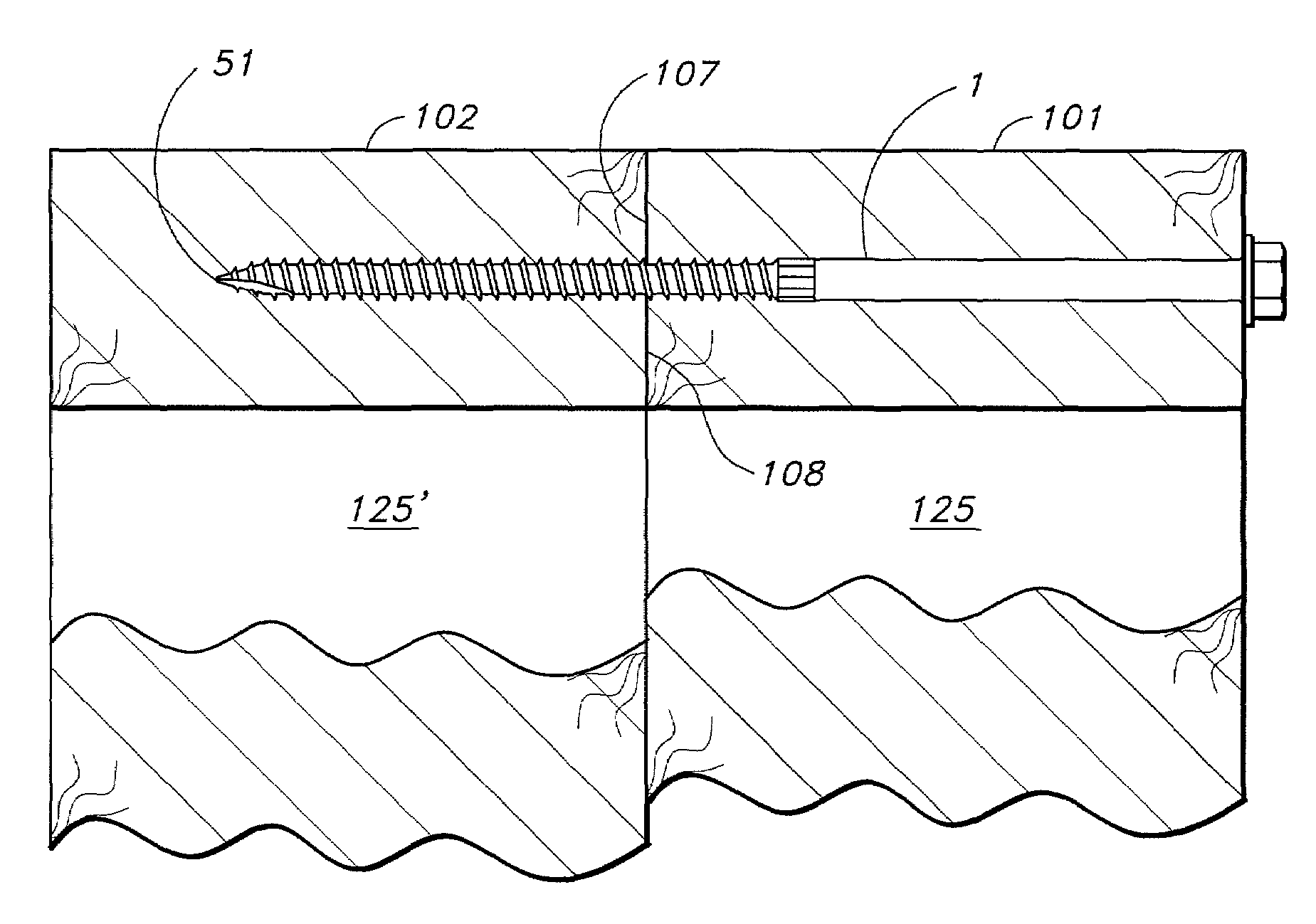
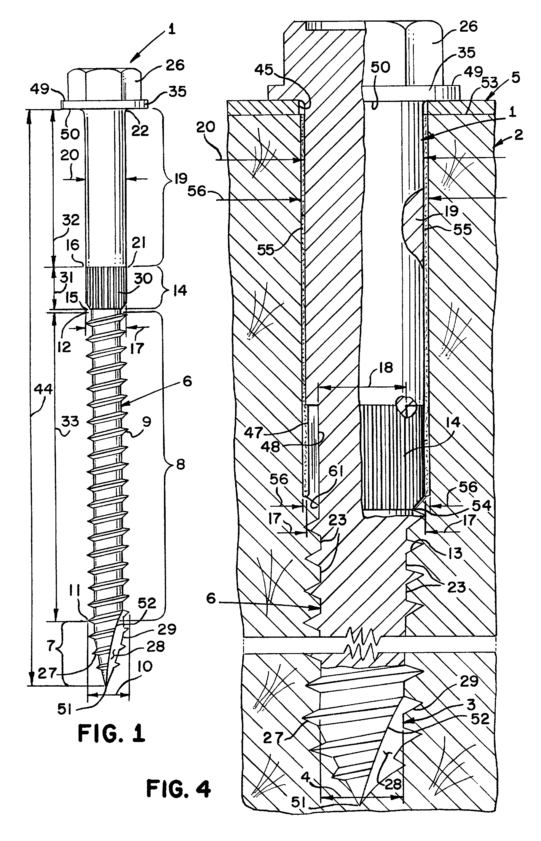
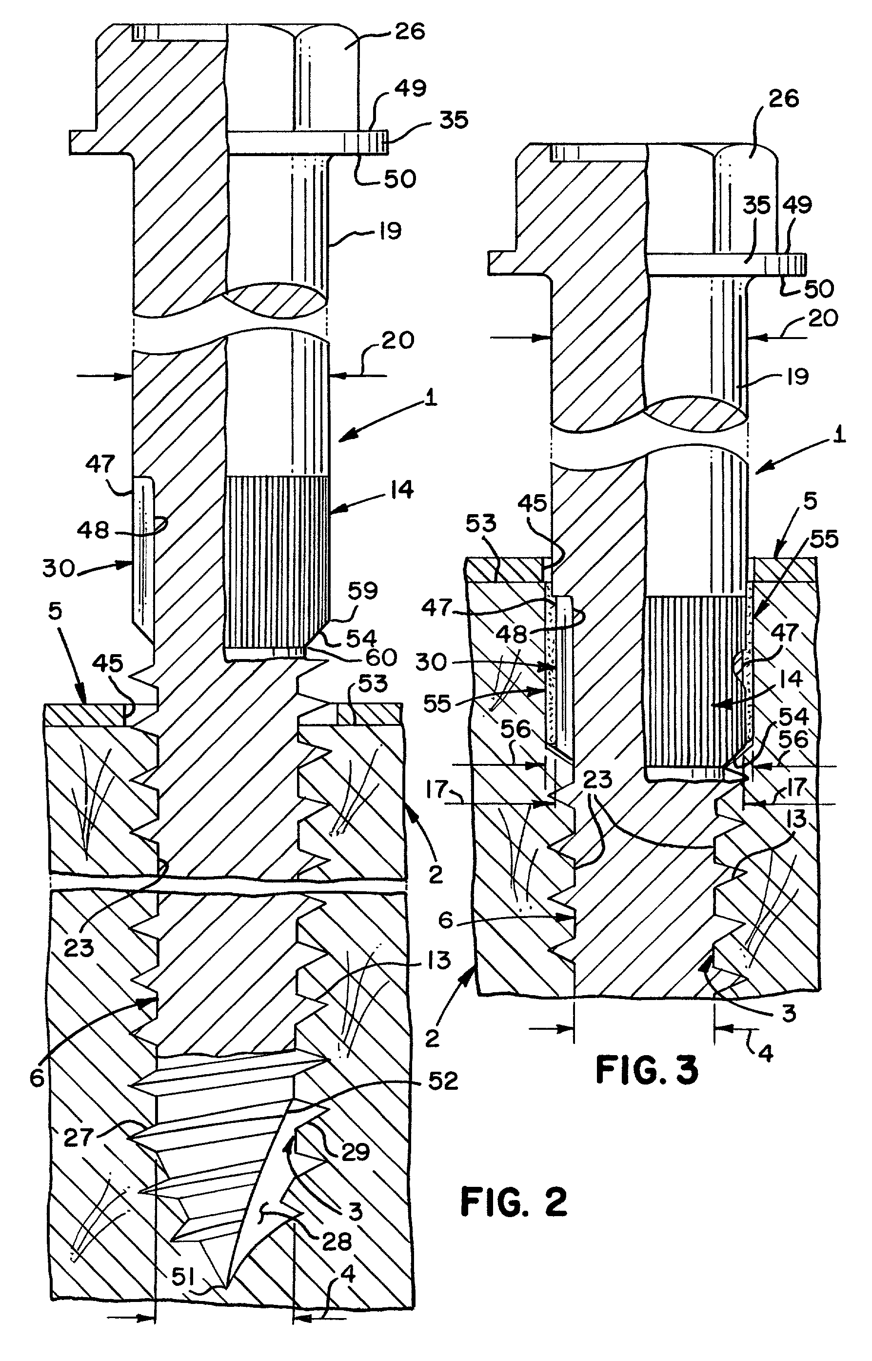
[0038]Referring to the drawings, and in particular FIGS. 1 and 6, the wood screw 1 of the present invention is adapted to hold a wood structural member 2 formed with a first bore 3 to a sheet metal member 5 or a first wood member 101 to a second wood member 102 in shear.

[0039]While the wood screw 1 of the present invention has excellent pull out value, the design is primarily directed to resisting shear forces. Three examples of environments in which the wood screw of the present invention is subject to shear forces are illustrated in the drawings.

[0040]Referring to FIG. 5, wood screw 1 connects a retrofit holdown device 36 to a wood sill member 37 resting on concrete foundation 38. Wood screw 1 is inserted through opening 45′ in sheet metal member 5′. A bolt 39 connects the retrofit holdown device 36 to foundation 38. Arrow 40 represents an upward force exerted on wood sill member 37 which may occur during either an earthquake or a high wind force such as a hurricane. Such an upwar...


PUM

PropertyMeasurementUnit
Lengthaaaaaaaaaa
Diameteraaaaaaaaaa

Abstract

Screw fasteners are used to connect multiple trusses in side-by-side relationship. The screw fasteners join truss wood members which are in edge to edge relationship with the screws being driven through the edge of each wood member. The screws may be knurled screws as described in U.S. Pat. No. 6,109,850; lag screws, or standard screws. The connection may also join wood board members in edge-to-edge relationship when bending of the wood members is limited by a restraining structure.

Description

[0001]This application is a continuation-in-part both of prior application Ser. No. 09 / 487,981, filed Jan. 20, 2000, since abandoned, and of prior application Ser. No. 09 / 692,674, filed Oct. 18, 2000, since abandoned. Prior application Ser. No. 09 / 692,674 is a continuation-in-part of prior application Ser. No. 09 / 487,981, filed Jan. 20, 2000 and since abandoned. Prior application Ser. No. 09 / 487,981 is a continuation of prior application Ser. No. 08 / 920,417, filed Aug. 29, 1997 and issued as U.S. Pat. No. 6,109,850 on Aug. 29, 2000. Prior application Ser. No. 08 / 920,417 is a continuation of prior application Ser. No. 08 / 725,003, filed Oct. 1, 1996 and since abandoned.BACKGROUND OF THE INVENTION[0002]In regions of the country subject to earthquake and hurricane events, it is becoming increasingly common to provide metal straps and anchors for affixing wood frame structures to their concrete foundations. For many years manufacturers such as Simpson Strong-Tie Company, Inc. have design...

Claims


Application Information

Patent Timeline
IPC IPC(8): F16B25/00E04C3/02E04B1/00E04C3/16F16B25/10F16B35/04
CPCE04C3/16F16B25/0015F16B25/0057F16B25/0063F16B25/103F16B35/041E04B2001/2684
Inventor CRAWFORD, MARK G.PRYOR, STEVEN E.COMMINS, ALFRED D.
Owner SIMPSON STRONG TIE
Learn More