Container

a technology of container and sluice box, which is applied in the field of container, can solve the problems of high cost even for a temporary silo installation, takes at least 3 to 4 days to complete, and the ‘temporary’ silo arrangement can be expensive to install, so as to reduce the ground load, prevent overturning, and large surface area

Inactive Publication Date: 2010-11-16
INBULK TECH
View PDF12 Cites 4 Cited by
  • Summary
  • Abstract
  • Description
  • Claims
  • Application Information

AI Technical Summary

Benefits of technology

[0013]An advantageous feature of this invention is the use of a self cleaning air filter which operates under pressure during truck unloading, thereby reducing the filter area required. This can be achieved because the airflow from the tanker truck can be restricted at the filter outlet so that the pressure in the filter and silo rises to approximately half the tanker truck pressure. Filters of the type used for the truck unloading are fabric and are designed to have a maximum flow through each m2 of fabric based on filtration velocity. A typical filtration velocity being 1.5 m3 / min / m2 of filter area for most powders. If the pressure in this filter is raised to 1 bar(g) for example, the amount of free air that this filter can pass is doubled because the air volume is halved if the absolute gas pressure is raised from 1 bar(a) to 2 bar(a), the effect of this being that the filter area can be halved. By restricting the air flow through the filter, the surge of airflow at the end of the truck unloading can also be avoided and this factor can also be used to further reduce the filter area. The net result being a filter of approximately ⅓ the filter area of a conventional silo. The result of this is that a filter of physically small size can now be used to vent the conveying air.
[0021]Normally a ground level filter would require a relatively large duct typically 200 mm to 300 mm diameter to carry the air and dust to the ground level mounted air filter which would have a bucket underneath to catch the dust from the filter. The ISO-Silo™ filter is provided with a much smaller pipe or duct, typically 100 mm diameter, due to the fact that it operates under pressure and has a flow limiting restriction on the filter outlet. To avoid the need to empty a bucket or container after the tanker unloads, the ISO-Silo™ filter may discharge its collected dust into the pneumatic transport pipe at the end of the truck unloading. This can be achieved because the filter unit is itself a pressure vessel. Compressed air can be applied to the filter to clean the filter and at the same time push collected dust into the pneumatic transport pipe.
[0025]In a further preferred embodiment of the invention after being filled by a pneumatic truck, the ISO-Silo™ itself can be pressurised to become a pneumatic conveying system that can convey either the powder or granular material to the point of use within a factory for example, thus avoiding the need for an additional transporting system that would be required with a conventional silo.
[0027]According to a further aspect of the invention there is provided an air filter for use on a vessel into which a bulk product is pneumatically conveyed, said air filter being provided with means of restricting the air flow through the filter, thereby resulting in an elevation of pressure within the vessel to above atmospheric pressure.
[0031]When the ISO-Silo™ reaches its final destination, it is lifted vertically by a crane onto a concrete base. To avoid having to prepare concrete foundations to spread load and prevent overturning with wind, the ISO-Silo™ uses a pre-cast concrete base which arrives on site in two pieces so that it can be moved on a standard road vehicle or put inside a small standard ISO box type container. This base is designed with a large surface area to reduce ground load and is also designed to prevent overturning due to wind. This base can be placed very quickly onto a simple ‘hardcore’ bed of aggregate by the same crane used to lift the ISO-container upright onto the base.

Problems solved by technology

This results in high cost even for a temporary silo installation.
Because of the need for prepared foundations and the construction of onward conveying systems, the ‘temporary’ silo arrangement can be expensive to install and takes at least 3 to 4 days to complete after foundations have been completed.
This adds to the total project cost.
Planning permission may also be required for this fixed installation which could take many months to get.
Ladder and filter units are easily damaged and these silos cannot be moved on intermodal transport such as that used for containers or lifted with container handling devices.

Method used


Image

  • Container
  • Container
  • Container

Examples


Embodiment Construction

[0038]The present invention will now be described in further detail, with reference to the accompanying drawings.

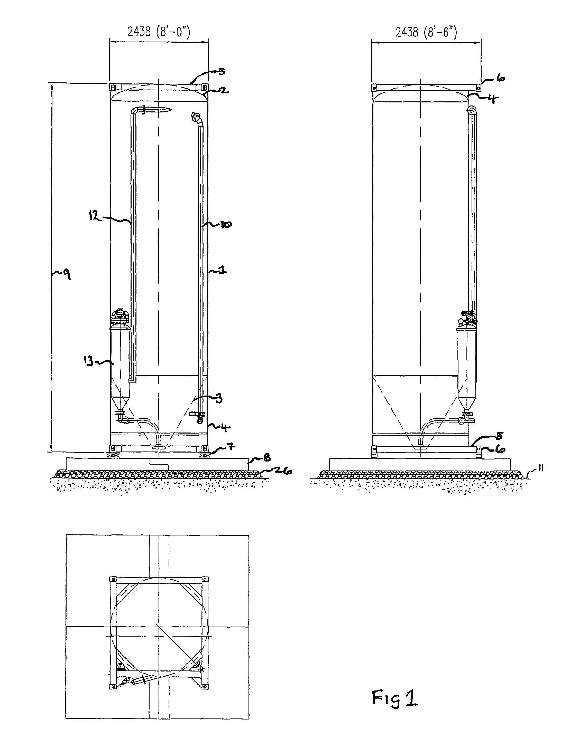
[0039]Referring to FIG. 1 of the accompanying drawings, a cylindrical pressure vessel 1 has a domed upper end 2 and a lower conical discharge section 3 which lies within extensions 4 to the vessel 1. Vessel 1 has end frames 5 which are dimensioned to comply with standard ISO container design codes. Corner blocks 6 are used to lift and locate the ISO-Silo™ on container handling equipment. The complete assembly is mounted on load cells 7 which are fixed to base 8 which is on top of hardcore 26.

[0040]The height 9 of the unit can be any standard container length for example 20 ft, 30 ft or 40 ft.

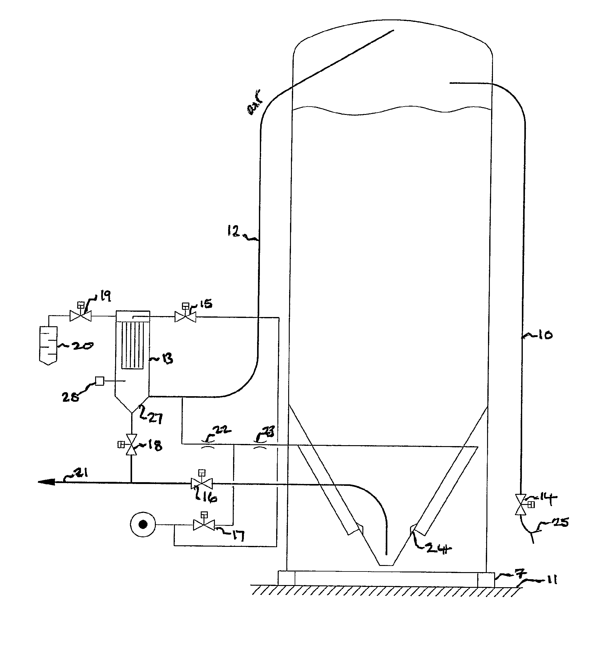
[0041]Tanker filling pipe 10 extends from near ground level 11 to the top of the vessel. Venting pipe 12 takes vented air from the vessel top to the venting filter 13 located near ground level.

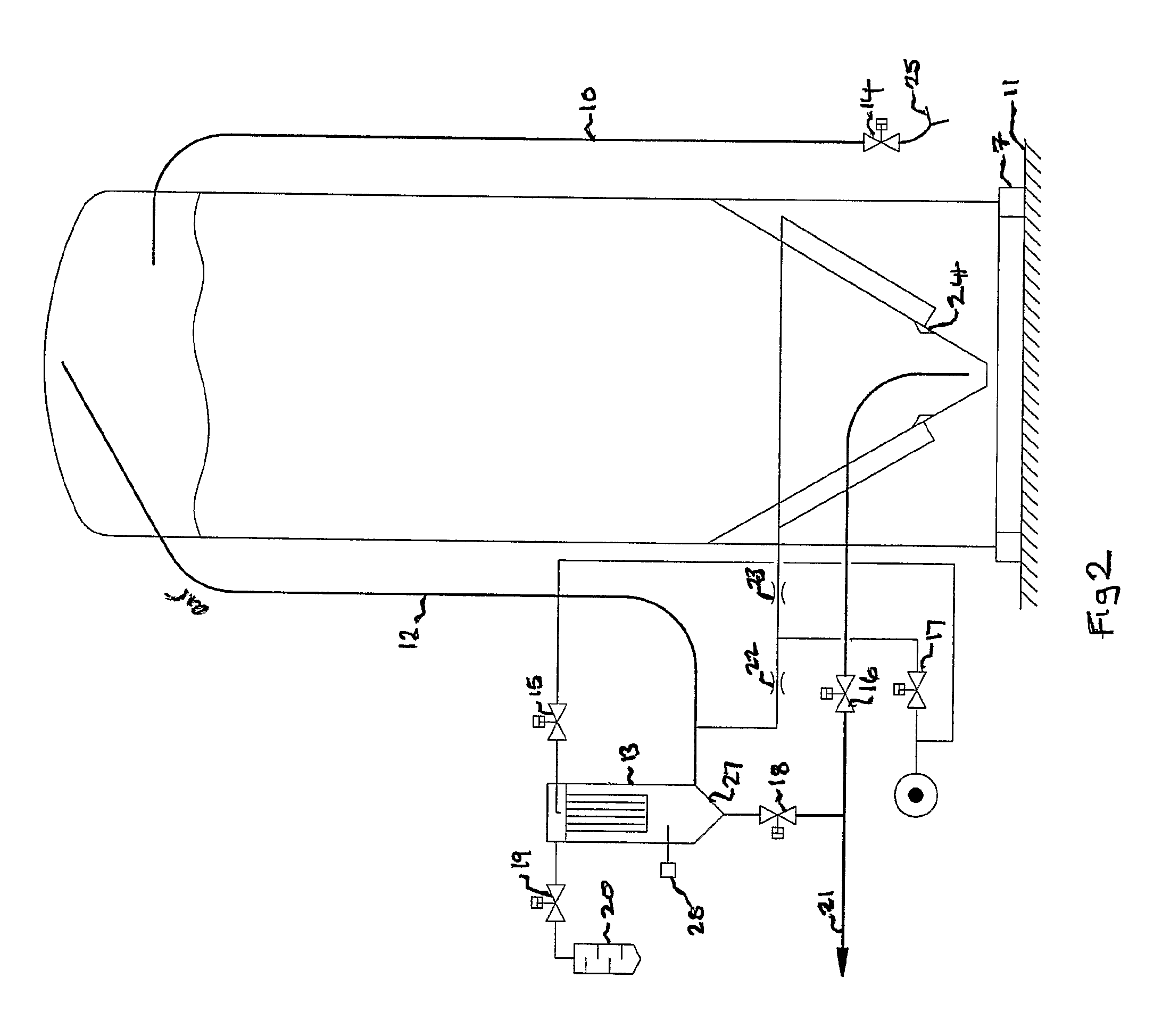
[0042]Referring to FIG. 2 of the accompanying drawings, the filling operation of the ISO-Sil...


PUM

PropertyMeasurementUnit
flow velocityaaaaaaaaaa
pressureaaaaaaaaaa
areasaaaaaaaaaa

Abstract

Containers, particularly to containers for storing dry granules and powders, for examples silos. A container can include an air filter for cleaning the air that pneumatically conveys bulk product into the container. A valve can be used to restrict the air flow through the air filter, thereby elevating the pressure within the container to above atmospheric pressure.

Description

BENEFIT CLAIMS[0001]This application is a U.S. National Stage of International Application No. PCT / GB2006 / 001399, filed 19 Apr. 2006, which claims the benefit of GB 0508113.8, filed 22 Apr. 2005.FIELD OF THE INVENTION[0002]The invention relates to containers, particularly to containers for storing dry granules and powders, for examples silos.BACKGROUND TO THE INVENTION[0003]Transportable silos for dry granules and powders that are filled by pneumatic tank trucks after installation have been known for many years. They consist of a thin metal silo which is designed to hold the bulk powder or granular product. A fixed tanker unloading pipe extends from near ground level to the silo top. A flexible hose is connected between the pneumatic tank truck and the tanker unloading pipe and the tank is then pressurised to pneumatically convey the contents of the truck in the silo. Pneumatic tank trucks are designed to operate at either 1 bar(g) or 2 bar(g).[0004]The air used for transporting the...

Claims


Application Information

Patent Timeline
Patent Type & Authority Patents(United States)
IPC IPC(8): B01D50/00B65D88/30B65D90/00B65G53/60
CPCB65D88/30B65D90/00B65G53/22B65G53/60B65D88/12
Inventor SNOWDON, BRIAN
Owner INBULK TECH
Why Eureka
Try Eureka