
Fixed plate frame microfiltration device

A fixed plate and filter technology, which is applied in the direction of fixed filter elements, filtration separation, chemical instruments and methods, etc., can solve the problems of floor area, installed power cost, maintenance cost and operation cost, etc., and achieve compact structure , high efficiency and space-saving effect

Active Publication Date: 2013-01-16
广州市地龙环保技术有限公司
View PDF4 Cites 2 Cited by
  • Summary
  • Abstract
  • Description
  • Claims
  • Application Information

AI Technical Summary

Problems solved by technology

Therefore, a large sewage treatment plant needs to install a large number of microfilters to meet the processing capacity requirements, which leads to relatively large equipment installation area, installed power, construction cost, maintenance cost and operating cost, and the treatment scale of the sewage treatment plant There is also a tendency to continue to expand. For example, the total scale of the fourth phase of Guangzhou Liede Wastewater Treatment Plant will reach 1.2 million m 3 / d

Method used


Image

  • Fixed plate frame microfiltration device

Examples


Embodiment 1

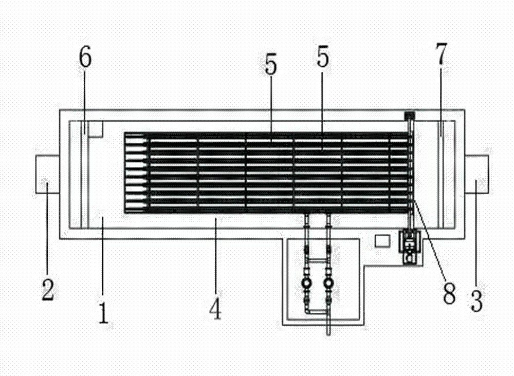
[0029] Such as figure 1 A fixed plate and frame microfiltration device shown includes a filter tank 1, an inlet pipe 2, an outlet pipe 3 and a square filter frame 4, a water distribution weir 6, an outlet weir 7, an isolation dam 8, an inlet pipe 2 and a square filter frame 4. The water outlet pipes 3 are arranged outside the two ends of the filter tank 1 respectively, and the filter frame body 4 is located in the filter tank 1. The filter frame body 4 is composed of nine square filter plates 5, which are arranged in parallel and at intervals, and the outer layer of the filter plate Wrapped with fiber microfiltration cloth, a water distribution weir 6 is arranged between the water inlet pipe 2 and the filter frame 4. The water distribution weir 6 is located inside the filter tank 1, close to the water inlet pipe 2, and close to the water outlet pipe 3. A water outlet weir 7 is arranged inside the filter tank 1 on one side, and an isolation dam 8 is also arranged between the wa...

Embodiment 2

[0032] This embodiment is basically the same as Embodiment 1, the difference is that a slot that can be matched with the filter plate 5 is provided at the bottom of the filter tank 1, and the filter plate 5 is fixed in the filter tank through the slot, which facilitates the filtering of the filter plate. , Replacement and removal of filter cloth.

Embodiment 3

[0034] This embodiment is basically the same as Embodiment 2, the difference is that in this embodiment, support brackets are set in the gaps between the square filter plates 5, and cleaning tips are added to the support brackets, so as to facilitate instant cleaning of the filter plates on site. cloth without removing the filter cloth.


PUM


Abstract

The invention relates to a water treatment device, in particular to a fixed plate frame microfiltration device. The device comprises a filter tank, a water inlet pipeline, a water outlet pipeline and a square filter frame body, wherein the water inlet pipeline and the water outlet pipeline are respectively arranged outside the two ends of the filter tank; and the filter frame body is arranged in the filter tank. The device has the advantages that (1) the effective area of a rectangular filter disc is large, and the space utilization rate is greatly improved; (2) a square plate frame filter disc is fixed and is not required to be rotated, the height of the filter disc is limited by transport dimensions, and the length of the filter disc is not limited; (3) by an immersion design, the utilization efficiency of the filter area under the immersion condition is the highest, and the treatment capacity of the microfiltration device is correspondingly high; and (4) by the scheme, the unit filter area can easily reach more than 300m<2>, even an ultra-large microfiltration device with the unit filter area of more than 600m<2> and the unit treatment capacity of more than 200,000m<3> / d (the treatment capacity in each square meter of filter area in each hour is 15m<3>) can be produced, and the unit scale can be continuously expanded.

Description

technical field [0001] The invention relates to a water treatment device, in particular to a fixed plate and frame microfiltration device. Background technique [0002] Microfiltration devices, also known as microfiltration machines, are equipment that use microporous filtration for water treatment. Microfiltration is a mechanical filtration method, which is suitable for separating the tiny suspended substances in the liquid, mainly phytoplankton, zooplankton and organic residues, to achieve the purpose of liquid purification or recovery of useful suspended substances. [0003] According to the emission standards of "Pollutant Discharge Standards for Urban Sewage Treatment Plants" GB18918-2002, the best discharge index after sewage treatment is the first-class A standard. The treated sewage is only discharged into the river directly according to the first-class B standard. When it is used for drinking water, landscape water, green land irrigation and other purposes, it need...

Claims


Application Information

Patent Timeline
Patent Type & Authority Applications(China)
IPC IPC(8): B01D29/50B01D29/62
Inventor 温伟聪
Owner 广州市地龙环保技术有限公司
Learn More