Particle therapy system

a particle therapy and system technology, applied in the field of particle therapy system, can solve the problem of limited space for imaging, and achieve the effect of optimal spacing

Inactive Publication Date: 2010-11-16
SIEMENS AG
View PDF12 Cites 57 Cited by
  • Summary
  • Abstract
  • Description
  • Claims
  • Application Information

AI Technical Summary

Benefits of technology

[0018]The imaging position is located between the patient positioning device and the irradiation position. The travel distance from the imaging position to the irradiation position and back is short. The patient positioning device is controlled, for example, by a monitoring system, which implements a suitable therapy plan and which may bring about the change of position between the imaging position and the irradiation position.
[0021]In one embodiment, the distance between the irradiation isocenter and the imaging center may be equal to or less than 2 m, preferably less than 1 m and if possible less than 0.5 m. During an irradiation, the position verification may be done multiple times. For example, without major loss of time from long travel distances. The imaging center, for example, may be at or nearly at the minimum spacing from the irradiation isocenter. The displacement of the patient may be as little as possible.

Problems solved by technology

There may be only a limited amount of space for the imaging.

Method used


Image

  • Particle therapy system
  • Particle therapy system
  • Particle therapy system

Examples


Embodiment Construction

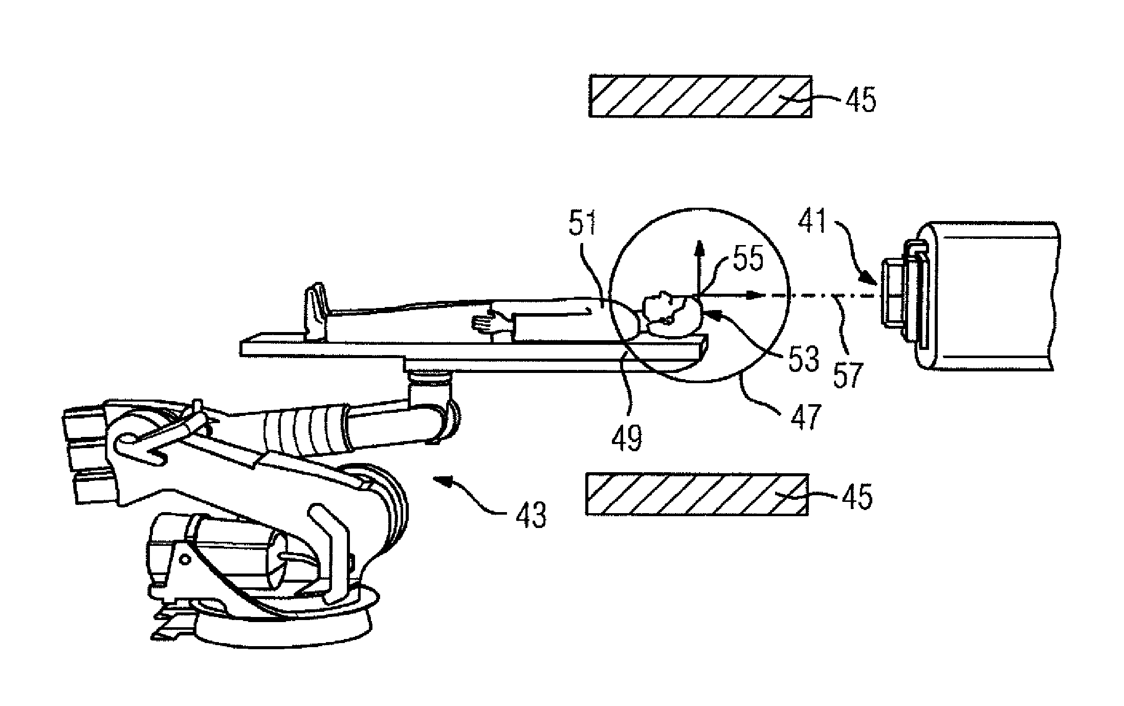
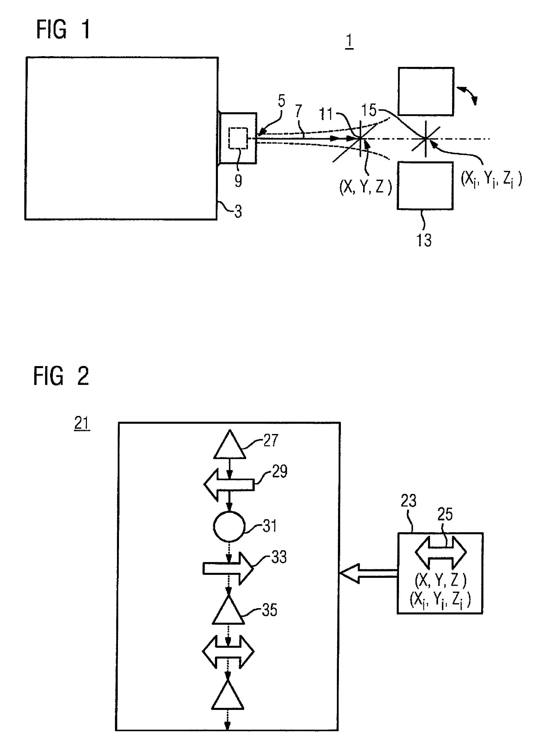
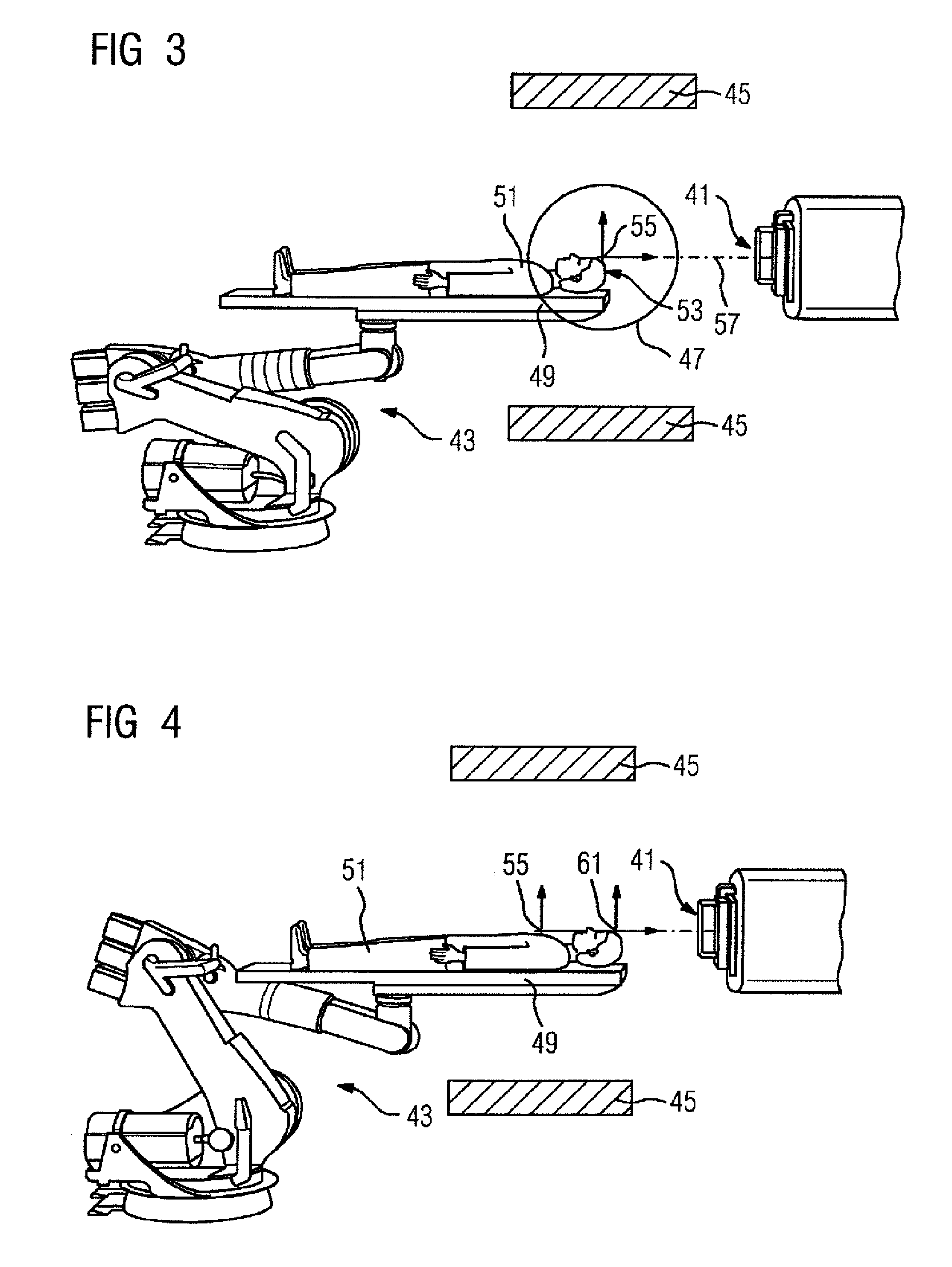
[0029]FIG. 1 shows a particle therapy system (installation) 1 for irradiating a volume of a patient with high-energy particles. The system 1 includes a particle accelerator system 3 that emits a particle beam 7 from a beam exit 5. The particle therapy system 1 may include a raster scanner 9 that may scans a region, for example, of 40 cm×40 cm. An isocenter 11 may be located centrally in the scanning region. The particle beam 7 diverges because of scattering processes in the beam or with the material being scanned. The isocenter is located as close as possible to the beam exit 5, so that irradiation may be done with the smallest possible beam diameter. During irradiation with protons, a spacing of 60 cm may be selected. At 60 cm, the beam diverges to the desired beam size assumed in the therapy plan. For example, the irradiation is done with a raster scanning method and a beam diameter of approximately 3 to 5 mm.

[0030]The particle therapy system 1 may include an imaging device 13. Th...


PUM


Abstract

A particle therapy system for irradiating a volume of a patient to be irradiated with high-energy particles is provided. The system includes a radiation outlet of a radiation delivery and acceleration system from which a particle beam exits in order to interact with the patient positioned in an irradiation position; an imaging device for verifying the position of the volume to be irradiated in relation to the particle beam; and a patient-positioning device with which the patient can be brought into the irradiation position for irradiation. The imaging device checks the position of the volume to be irradiated in an imaging position of the patient that is spatially remote from the irradiation position, and the patient-positioning device automatically changes position between imaging position and irradiation position.

Description

[0001]The present patent document is a §371 continuation of PCT Application Serial Number PCT / EP2006 / 068228, filed Aug. 11, 2006, designating the United States, which is hereby incorporated by reference. This patent document also claims the benefit of DE 10 2005 053719.7, filed Oct. 11, 2005.BACKGROUND[0002]The present embodiments relate to a particle therapy system.[0003]A particle therapy system (installation) may be used to irradiate a patient with a particle beam. H. Blattmann in “Beam delivery systems for charged particles,” Radiat. Environ. Biophys. (1992) 31:219-231 discloses various irradiation systems and techniques. EP 0 986 070 discloses a particle therapy system.[0004]Japanese Patent Disclosure JP 11009708 A discloses an irradiation therapy system, in which a patient positioning device is located between a magnetic resonance scanner and the gantry of a treatment system.[0005]A particle therapy system includes an accelerator unit and a high-energy beam guiding system. A s...

Claims


Application Information

Patent Timeline
Patent Type & Authority Patents(United States)
IPC IPC(8): G01G5/00
CPCA61N5/103A61N5/1043A61N5/1049A61N5/1069A61N5/1078A61N2005/1061A61N2005/1063A61N2005/1087
Inventor GRÖZINGER, SVEN OLIVERHERRMANN, KLAUSRIETZEL, EIKESOMMER, ANDRESZEUNER, TORSTEN
Owner SIEMENS AG
Why Eureka
Try Eureka