
Retro-directive ground-terminal antenna for communication with geostationary satellites in slightly inclined orbits

a geostationary satellite and ground-terminal technology, applied in antennas, antenna details, electrical equipment, etc., can solve the problems of satellite orbit drifting away, severe signal loss, bulk, complexity, etc., and achieve high gain

Active Publication Date: 2010-11-16
SPATIAL DIGITAL SYST
View PDF10 Cites 9 Cited by
  • Summary
  • Abstract
  • Description
  • Claims
  • Application Information

AI Technical Summary

Benefits of technology

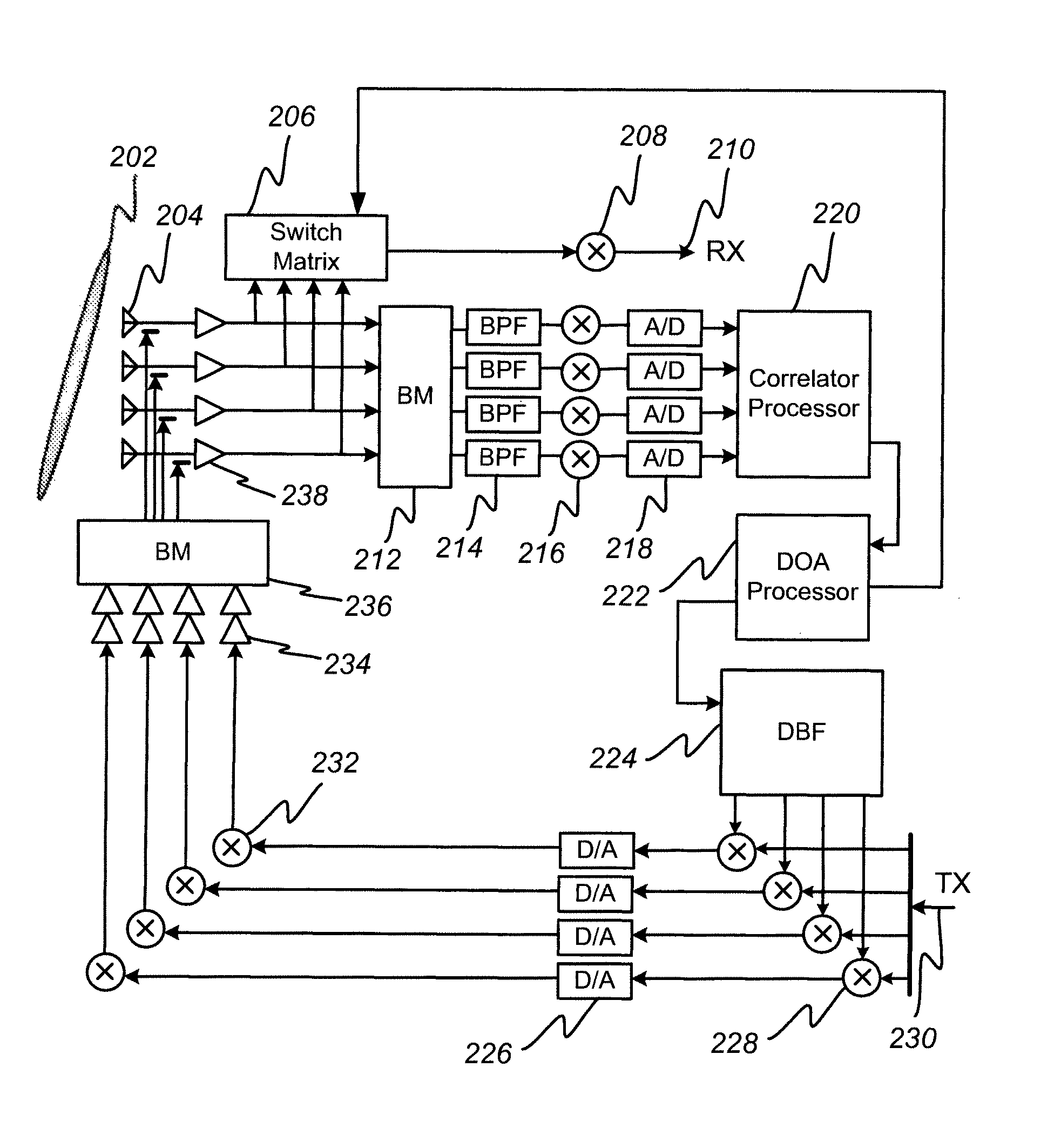
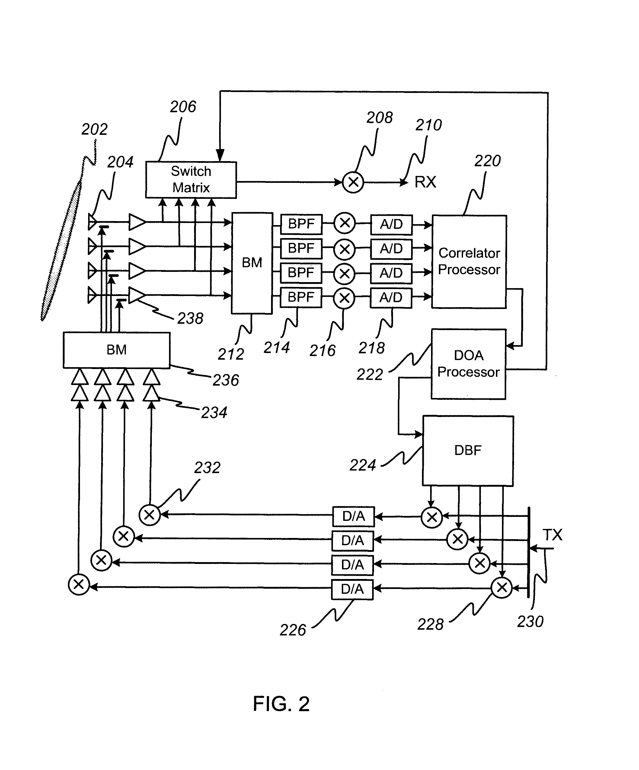
[0010]A system is provided that autonomously detects a direction of arrival of a signal from a geostationary satellite and generates a transmit signal that is sent along the same direction back toward the satellite. The system maintains high gain in the direction of the satellite and tracks its motion without the need for a mechanical pointing system.
[0012]A parabolic reflector typically has a limited scan range, and far-field beams arriving from directions that are a few degrees off of boresight will focus at locations that are slightly offset from the boresight focus of the antenna. Thus, energy arriving from off-boresight angles will preferentially illuminate elements of the array feed that are positioned slightly away from the reflector focus. Similarly, energy radiated from feed array elements that are located slightly off focus will result in far-field beams that are pointed in directions a few degrees off of boresight. Thus, for a fixed boresight direction, an array feed allows for electronic scanning of the antenna beam within the limited scan range of the parabolic reflector. In the case of geostationary satellites that are inclined by a few degrees from the equator and thus move in a north-south direction relative to the ground terminal during the course of each day, a feed array oriented in the north-south, or elevation direction will allow the motion of the satellite to be tracked without mechanically moving the boresight pointing direction.
[0021]In an alternative embodiment of a retro-directed antenna terminal in accordance with the present invention, orthogonal coding is used to simplify the radio-frequency hardware and to eliminate the need for multiple down- and up-conversion stages and multiple A / D and D / A converters. In this alternative embodiment, the received signals from four array feed elements are routed through a Butler Matrix or other radio-frequency FT processor. The four transformed outputs are then routed to four bi-phase modulators, each of which is driven by a separate mutually orthogonal pseudonoise (PN) code produced by a code generator. The four modulated beams are then summed, and the composite beam is frequency down-converted by a single down-converter and digitized by a single A / D converter. The sampled composite beam is then routed through four matched filters, each of which correlates the sample stream with one of the PN sequences. Because of the mutual orthogonality of the PN sequences, only that portion of the composite beam that was originally modulated with the corresponding PN sequence will be recovered by the matched filter. Thus, this process allows for the recovery of four separate digital data streams while requiring only one down-conversion chain and one A / D. This not only reduces RF parts count and complexity but also eliminates problems of poorly matched analog channels that can degrade performance.
[0022]The digital samples are processed by a direction-of-arrival processor as before, and a DBF processor again calculates BWVs corresponding to the measured phase slope and direction of arrival. In addition to using the BWVs to perform transmit-side beam forming, the BWVs are also used to multiply the receive data streams coming out of the matched filters. This operation recovers the coherent sum of the feed array elements for the direction of arrival of the wavefront from the satellite and thus is a fully digitized primary receiver signal that can be routed to the primary receiver of the system, such as a digital television receiver or similar device. Thus, the need for a separate analog switch matrix and separate down-conversion chain is also eliminated.

Problems solved by technology

However, while a satellite in geostationary orbit should theoretically remain at a fixed location in the sky, perturbations to its orbit caused by interactions of the Sun and Moon as well as the non-spherical shape of the Earth itself cause the orbit of the satellite to drift away from its fiducial geostationary point.
This motion can result in severe loss of signal by a ground terminal with a simple fixed antenna.
A number of methods to address this problem have been developed, but all have significant drawbacks.
However, such a solution adds significant cost, bulk, and complexity and is not suitable for applications requiring a large number of ground stations, such as direct-broadcast television.
However, stretching the radiation pattern significantly reduces antenna gain, negatively impacting receive performance and requiring additional power for transmit.
When the satellite runs out of fuel, it can no longer be maintained in geostationary orbit, so the frequency of such maneuvers directly affects the useful life of the satellite.

Method used


Image

  • Retro-directive ground-terminal antenna for communication with geostationary satellites in slightly inclined orbits
  • Retro-directive ground-terminal antenna for communication with geostationary satellites in slightly inclined orbits
  • Retro-directive ground-terminal antenna for communication with geostationary satellites in slightly inclined orbits

Examples


Embodiment Construction

[0033]The invention provides a simple, low-cost, limited-scan-angle, retro-directive antenna featuring an array feed capable of steering the antenna pattern to track orbital excursions of a geostationary satellite in an orbit inclined with respect to the equator by several degrees. In the detailed description that follows, like element numerals are used to indicate like elements appearing in one or more of the figures.

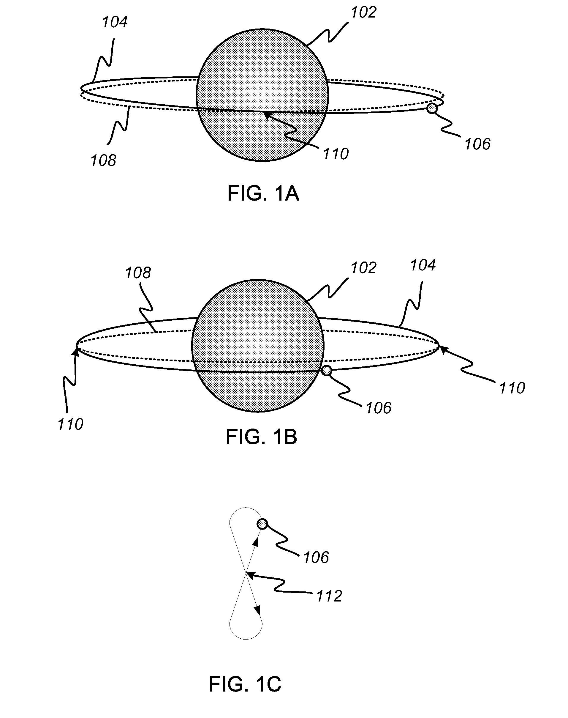
[0034]FIGS. 1A-C depict the motion of a typical geostationary satellite 106 in orbit around the Earth 102. The ideal geostationary orbit 108 lies directly above the Earth's equator and results in the satellite's appearing stationary in the sky with respect to an observer on the ground. Due to gravitational perturbations, the actual orbit 104 of the satellite drifts, becoming inclined by up to several degrees with respect to the equator. Periodic station-keeping maneuvers are undertaken to bring the actual orbit back toward an inclination of zero degrees. The inclined o...


PUM


Abstract

A retro-directive antenna for communicating with a geostationary satellite autonomously detects the direction from which a signal is received, and transmits a beam that points back along the same direction. An array feed is used to illuminate a parabolic reflector. Each feed element of the retro-directive antenna is associated with a unique pointing direction of the beam in the far field. As the transmit energy is switched to different feed elements, the far-field beam is scanned, making it possible to track a geostationary satellite in a slightly inclined orbit. This eliminates the need for mechanical tracking and maintains high antenna gain in the direction of the geostationary satellite. The use of a toroidal reflector with multiple linear array feeds spaced in the azimuth direction enables multi-beam operation, allowing multiple geostationary satellites, spaced by up to fifteen beam widths in azimuth, to be tracked simultaneously and independently.

Description

RELATED APPLICATION DATA[0001]This application claims the benefit, pursuant to 35 U.S.C. §119(e), of U.S. provisional application Ser. No. 60 / 930,956, filed May 21, 2007.BACKGROUND OF THE INVENTION[0002]1. Field of the Invention[0003]The present invention relates to ground-terminal antennas for communicating with satellites in geostationary orbit. More particularly, it relates to low-cost, electronically steerable antennas adapted to compensate for motion of a satellite with respect to its fiducial geostationary position, and to electronically steerable multi-beam antennas adapted to compensate for motions of multiple satellites simultaneously.[0004]2. Description of Related Art[0005]Satellites in geostationary orbit are widely used for communications and broadcast applications. When the orbit of a satellite lies along a path 35,786 km directly over the equator, its orbital velocity exactly matches the rate of rotation of the Earth, and the satellite remains fixed in the sky relativ...

Claims


Application Information

Patent Timeline
Patent Type & Authority Patents(United States)
IPC IPC(8): H01Q1/00H01Q3/00
CPCH01Q3/2605H01Q3/2647H01Q3/46H04B7/086H01Q3/24H04B7/0615
Inventor CHANG, DONALD CHIN-DONG
Owner SPATIAL DIGITAL SYST
Learn More