X-ray tube, x-ray system, and method for generating x-rays

a technology of x-ray tubes and x-ray systems, applied in the direction of x-ray tubes, x-ray tube cathode assembly, x-ray tube cooling, etc., can solve the problems of hard to realize power peaks with commonly used x-ray tubes, and achieve simple and easy manufacturing, optimized intensity profile, and easy tilting

Inactive Publication Date: 2010-11-16
KONINK PHILIPS ELECTRONICS NV
View PDF9 Cites 10 Cited by
  • Summary
  • Abstract
  • Description
  • Claims
  • Application Information

AI Technical Summary

Benefits of technology

[0010]By generate an electron beam having an energy or intensity distribution over the focal spot which distribution is asymmetric it may be possible to reduce the maximum temperature as well as the mean temperature the anode is exposed to. Thus, it might be possible to increase the intensity of the power peaks of the x-ray tube without the necessity to increase either the anode diameter and / or to increase a rotating speed of the anode, which necessity may be given by a commonly used x-ray tube. Thus, the limiting factor of mechanical stability of the anode may be bypassed by using an x-ray tube according to an exemplary embodiment.
[0028]The provision of a deflection angle between 0° and 2° and particular the provision of a deflection angle between 0.5° and 1° may be an efficient way to generate an asymmetric focal spot intensity profile on the rotatable anode, which may lead to a decreased maximum focal spot temperature.

Problems solved by technology

These power peaks are hard to realize with commonly used x-ray tubes.

Method used


Image

  • X-ray tube, x-ray system, and method for generating x-rays
  • X-ray tube, x-ray system, and method for generating x-rays
  • X-ray tube, x-ray system, and method for generating x-rays

Examples


Embodiment Construction

[0038]The illustration in the drawings is schematically. In different drawings, similar or identical elements are provided with similar or identical reference signs.

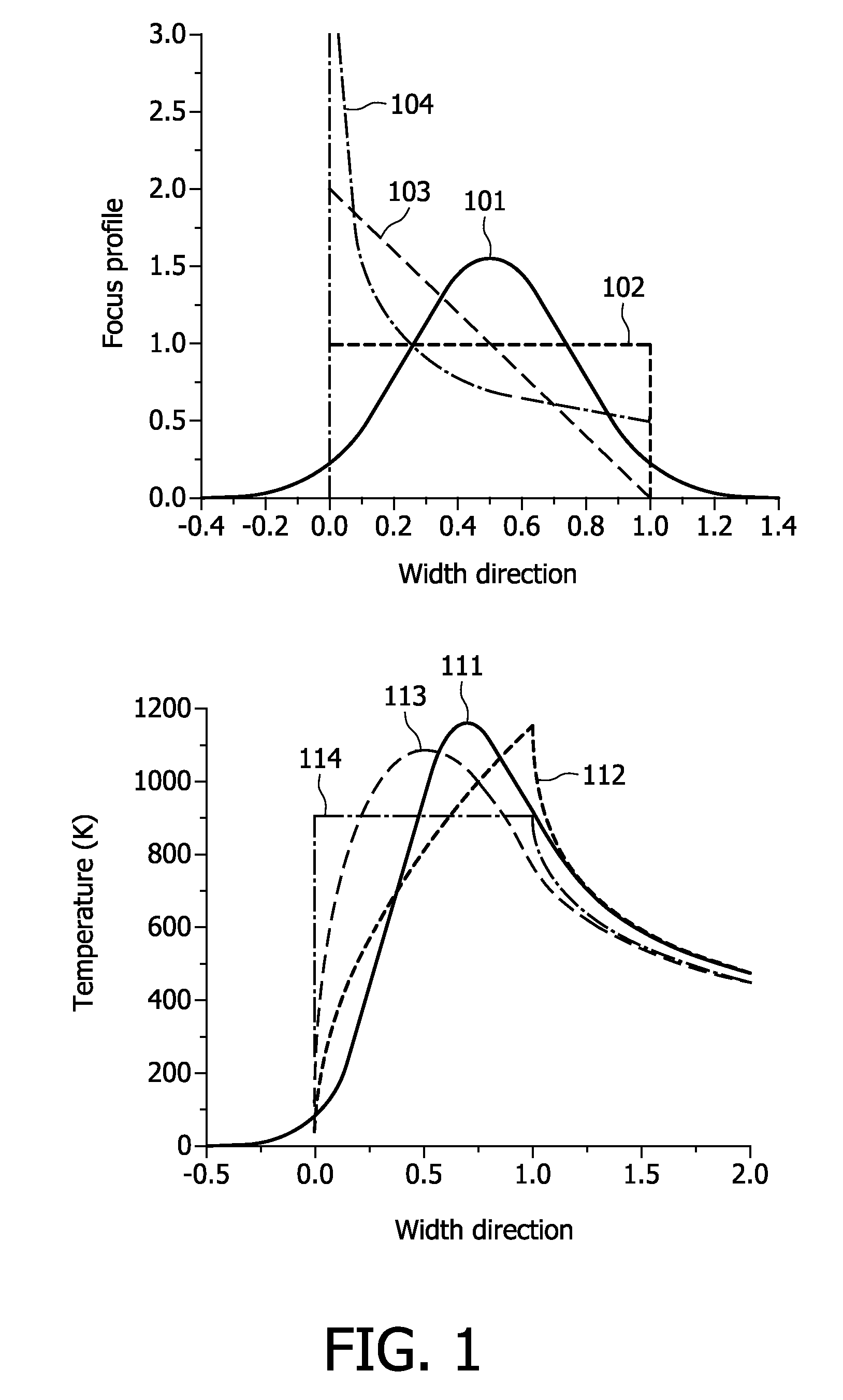
[0039]FIG. 1 shows schematic diagrams of different focal spot intensity profiles (FIG. 1A) and of resulting temperature profiles (FIG. 1B). The intensity profile is shown dependent on a width in circumferential direction of an anode of an x-ray tube. FIG. 1A shows the focal spot intensity for four different profiles over the width. The reference sign 101 refers to a Gaussian profile, i.e. an intensity profile according to a Gaussian distribution. The reference sign 102 refers to a constant profile, i.e. an intensity profile which exhibits a constant intensity value along the width of the focal spot. The constant intensity of this profile is set to the value of 1. The reference sign 103 refers to a linear profile, i.e. an intensity profile which exhibits a linear decrease in intensity over the width of the focal spot. The...


PUM


Abstract

According to an exemplary embodiment an x-ray tube comprises a cathode, rotable disc anode, and a focal spot modulating unit, wherein the cathode is adapted to emit an electron beam, and wherein the focal spot modulating unit is adapted to modulate the electron beam in such a way that an intensity distribution of the electron beam on a focal spot on the anode is asymmetric such that the intensity of the electron beam on the focal spot is higher at the front of the focal spot with respect to the rotation direction.

Description

FIELD OF INVENTION[0001]The invention relates to x-ray tubes, to x-ray systems and methods for generating x-rays. In particular the invention relates to x-ray tubes for x-ray systems like Computer Tomography comprising a rotatable disk anode, wherein a maximum peak temperature of an electron beam focal spot is reduced.TECHNICAL BACKGROUND[0002]One of the major demands for further Computer Tomography (CT) applications is to scan a heart during its passive state. Necessary for that is a faster gantry rotation and hence a shorter but higher x-ray power pulse. These power peaks are hard to realize with commonly used x-ray tubes. Computed tomography (CT) is a process of using digital processing to generate a three-dimensional image of the internal of an object under investigation (object of interest, object under examination). The reconstruction of CT images can be done by applying appropriate algorithms.SUMMARY OF THE INVENTION[0003]There may be a need to provide an improved x-ray tube,...

Claims


Application Information

Patent Timeline
Patent Type & Authority Patents(United States)
IPC IPC(8): H01J35/04H01J35/14H01J35/10
CPCH01J35/06H01J35/105H01J35/14H01J2235/064H01J2235/1225H01J35/153H01J35/24H01J35/147H01J35/066
Inventor HAUTTMANN, STEFANPIETIG, RAINERHORIKX, JEROEN JAN LAMBERTUS
Owner KONINK PHILIPS ELECTRONICS NV
Why Eureka
Try Eureka