
Automatic take-off method and device for an airplane

a technology of automatic take-off and airplane, which is applied in the direction of vehicle position/course/altitude control, process and machine control, instruments, etc., can solve the problems of pilot pulling too early on the control column, affecting the quality of guidance objectives, and affecting the accuracy of pilots' fligh

Active Publication Date: 2010-11-16
AIRBUS OPERATIONS (SAS)
View PDF14 Cites 9 Cited by
  • Summary
  • Abstract
  • Description
  • Claims
  • Application Information

AI Technical Summary

Benefits of technology

[0013]The object of the present invention is to remedy these drawbacks. It relates to an automatic take-off method for an airplane, which makes it possible to at least partly automate the take-off phase by proposing an automatic elevation guidance mode to ensure automatic rotation.

Problems solved by technology

In such a standard manual take-off, there arises the problem of the quality with which the guidance objectives are followed during the take-off.
Because of this, a greater or lesser time delay may occur between the moment when the pilot realizes that he has reached the rotation speed and the moment when he pulls on the control column.
In the opposite case, it may be that the pilot pulls too early on the control column.
In this case, the speed of the airplane does not allow it to take off, and the airplane continues to accelerate with the nose lifted.
This is reflected in a very significant drag, and also, a direct impact on the take-off distance.
Furthermore, with large airplanes, a risk of tailstrike on take-off must be taken into account.
It is, in fact, not rare to observe this type of incident in service, which normally results in a lengthy lay-up of the airplane.
If a sight guidance mode (as mentioned above) remains acceptable in clear weather, it becomes very difficult in reduced visibility conditions.
Similarly, the workload of the pilot greatly increases if an engine fails.

Method used


Image

  • Automatic take-off method and device for an airplane
  • Automatic take-off method and device for an airplane
  • Automatic take-off method and device for an airplane

Examples


first embodiment

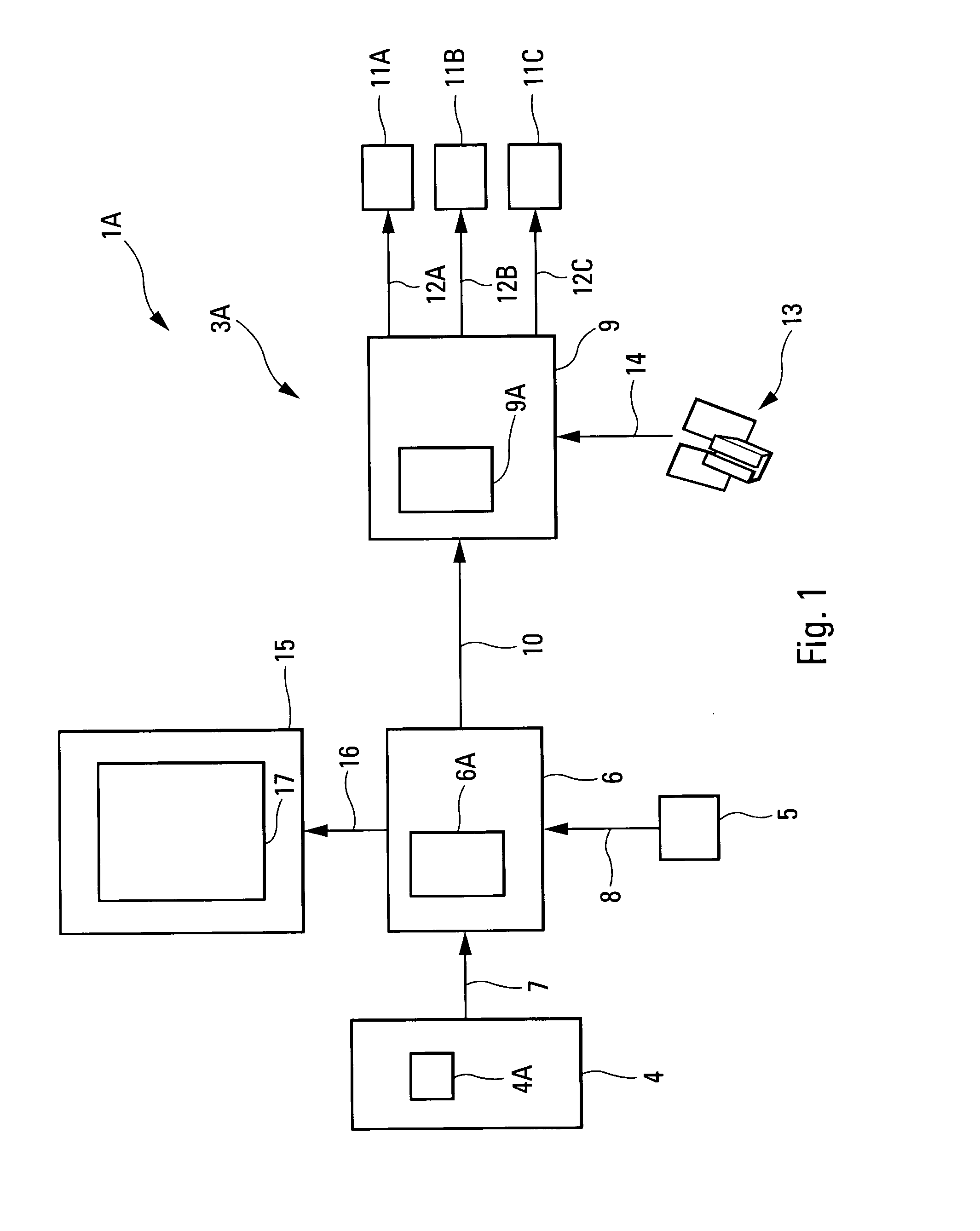
[0108]In the first embodiment represented in FIG. 1, which relates to a semi-automatic take-off, said device 1A which is onboard said airplane A comprises an automatic piloting assembly 3A which comprises:[0109]means 4 comprising means 4A, such as a flight management system of the FMS type for example, which are formed in such a way as to automatically determine an elevation guidance objective. According to the invention, this elevation guidance objective represents an angular profile along the pitch axis which makes it possible to obtain performance levels that are optimized according to particular take-off conditions (weight of the airplane A, engine failure, wind, etc.). This angular profile is expressed according to a first parameter. Preferably, this first parameter represents the trim θ of the airplane A. It can also be the angle of climb of the airplane A;[0110]standard means 5 for automatically measuring on the airplane A the current value of said first parameter;[0111]means...

second embodiment

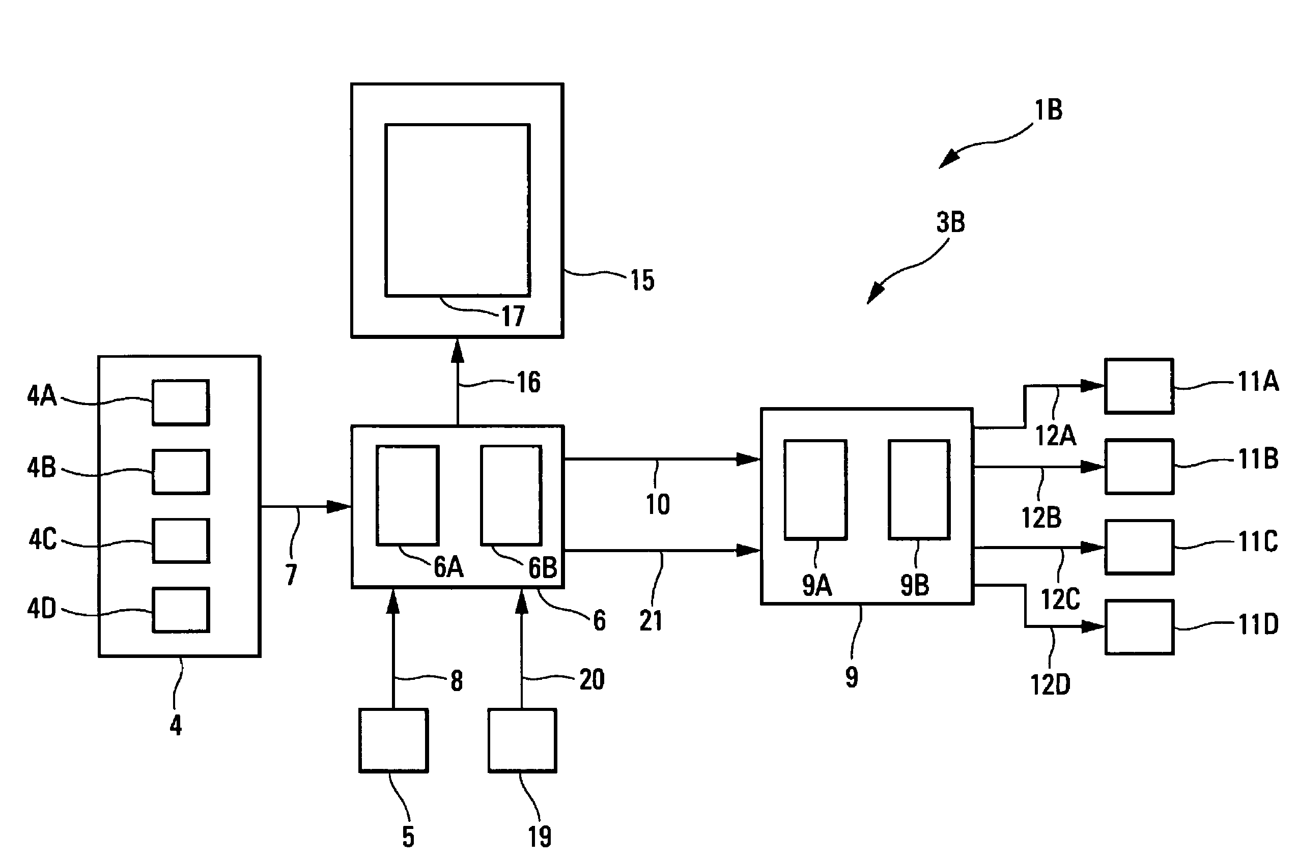
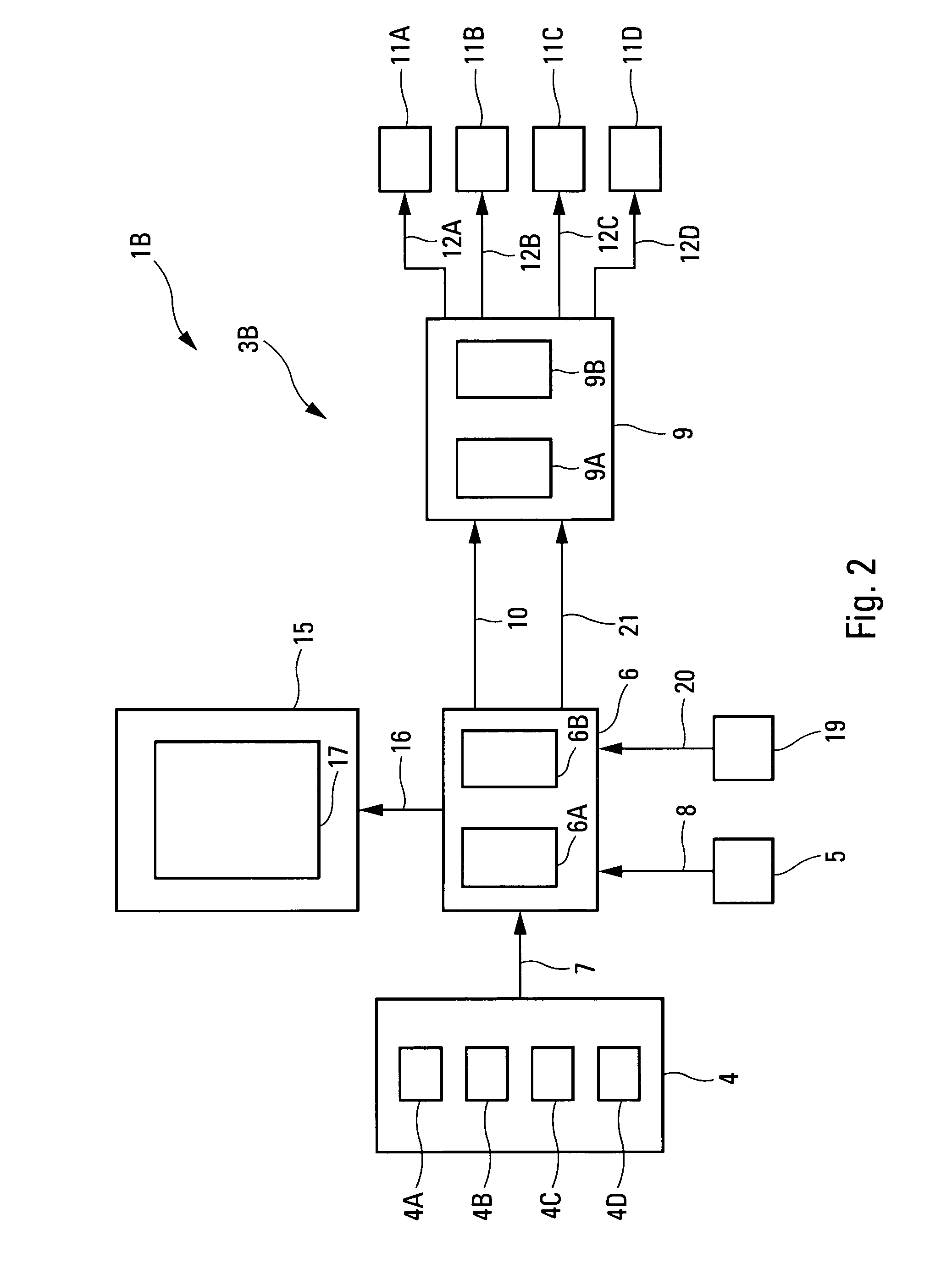
[0142]Moreover, in the second embodiment represented in FIG. 2, the device 1B is intended to perform a fully automatic take-off of the airplane A, that is, an automatic take-off in both the vertical plane and the lateral-plane.

[0143]To implement the automatic guidance of the airplane A in the vertical plane on the take-off, the device 1B comprises means similar to those used by the abovementioned device 1A to perform the same automatic elevation guidance. Thus, the means described with reference to FIG. 1 and included in FIG. 2 are not described further below.

[0144]On the other hand, in the lateral plane, the guidance is no longer performed manually by means of a rudder bar, but is implemented automatically by said device 1B.

[0145]For this, said device 1B notably comprises an automatic piloting assembly 3B which comprises in particular:[0146]means 4A, 4B, 4C, 4D specified below, which are incorporated in said means 4 and which are formed notably so as to automatically determine a la...


PUM


Abstract

Automatic take-off method and device for an airplane. The device includes a device for automatically determining, using an elevation guidance objective, a vertical piloting objective which is expressed as rate of pitch, and a device for automatically determining, using the vertical piloting objective, deflection commands for elevators of the airplane.

Description

TECHNICAL FIELD OF THE INVENTION[0001]The present invention relates to an automatic take-off method and device for an airplane, in particular a transport airplane.BACKGROUND OF THE INVENTION[0002]It is known that, since the start of civil aviation, the take-off of an airplane is handled manually by the airplane's pilot by means of piloting units (central control column or side-stick controller, rudder bar) that are specific to the airplane concerned. During this take-off phase, the crew is responsible for controlling the path of the airplane, both in the vertical plane and in the lateral plane (or horizontal plane). The crew has to follow theoretical guidance objectives (recommendation of the airplane's flight manual), visual guidance objectives (axis of the runway) and / or physical guidance objectives (for example, reference of an LOC-type antenna, specified below).[0003]In such a standard manual take-off, there arises the problem of the quality with which the guidance objectives ar...

Claims


Application Information

Patent Timeline
IPC IPC(8): G06G7/70
CPCG05D1/0661
Inventor VILLAUME, FABRICEJOURDAN, CHRISTOPHEJACOB, ARMANDBLONDIN, VINCENT
Owner AIRBUS OPERATIONS (SAS)
Learn More