Methods and apparatus for operating a pulse detonation engine

a pulse detonation engine and pulse technology, applied in the field of turbine engines, can solve the problem that known pulse detonation engines generally do not include pulse detonation chambers, and achieve the effect of facilitating mixing pulse detonation combustor air flow

Active Publication Date: 2010-11-23
GENERAL ELECTRIC CO
View PDF26 Cites 23 Cited by
  • Summary
  • Abstract
  • Description
  • Claims
  • Application Information

AI Technical Summary

Benefits of technology

[0006]In another aspect, a flow mixer for use with a pulse detonation combustor coupled to an axial turbine is provided. The flow mixer includes an inlet portion, an outlet portion, and a body portion extending therebetween. The inlet portion is configured to receive air flow discharged from the pulse detonation combustor and the body portion is configured to channel a bypass air flow circumferentially around the body portion. The outlet portion facilitates mixing pulse detonation combustor air flow with bypass air flow to produce a steady, uniform air flow towards the turbine.
[0007]In a further aspect, a pulse detonation engine is provided. The engine includes a pulse detonation combustor including at least one pulse detonation chamber that is configured to channel pulse detonation combustor air flow and bypass air flow towards an axial turbine. The engine also includes a flow mixer that is configured to receive and to mix the pulse detonation combustor air flow and the bypass air flow from the chamber to facilitate producing a steady, uniform air flow towards the turbine.

Problems solved by technology

However, known pulse detonation engines generally do not include pulse detonation chamber designs that are optimized to direct steady and spatially uniform flows to the turbine.

Method used


Image

  • Methods and apparatus for operating a pulse detonation engine
  • Methods and apparatus for operating a pulse detonation engine
  • Methods and apparatus for operating a pulse detonation engine

Examples


Embodiment Construction

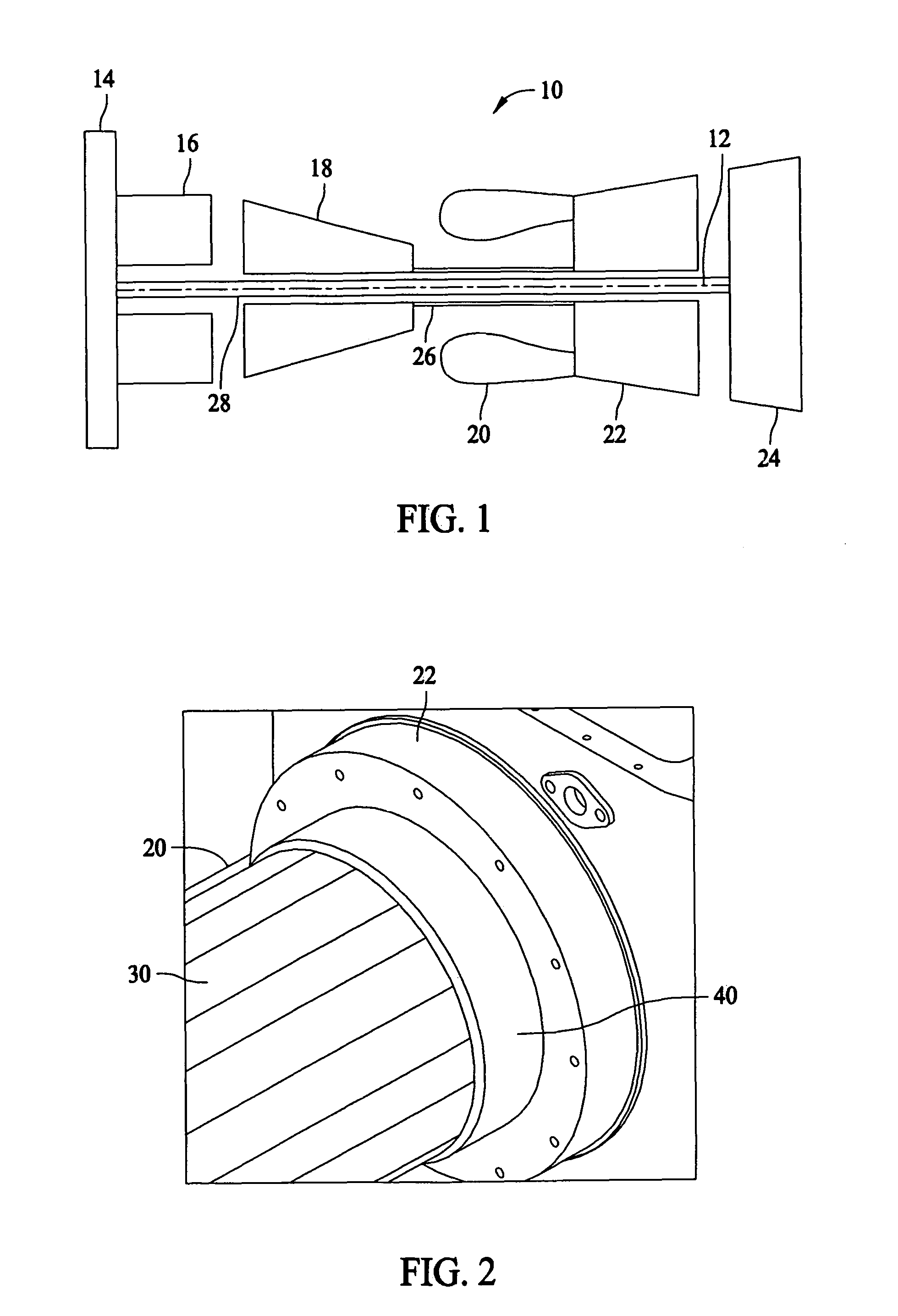
[0013]FIG. 1 is a schematic illustration of an exemplary hybrid pulse detonation-turbine engine 10. Engine 10 includes, in serial axial flow communication about a longitudinal centerline axis 12, a fan 14, a booster 16, a high pressure compressor 18, and a pulse detonation combustor (PDC) 20, a high pressure turbine 22, and a low pressure turbine 24. High pressure turbine 22 is coupled to high pressure compressor 18 with a first rotor shaft 26, and low pressure turbine 24 is coupled to both booster 16 and fan 14 with a second rotor shaft 28, which is disposed within first shaft 26.

[0014]In operation, air flows through fan 14, booster 16, and high pressure compressor 18, being pressurized by each component in succession. At least a portion of the highly compressed air is delivered to PDC 20 and secondary or bypass portion flows over each component to facilitate cooling each component. Hot exhaust flow from PDC 20 drives turbines 22 and / or 24 before exiting gas turbine engine 10.
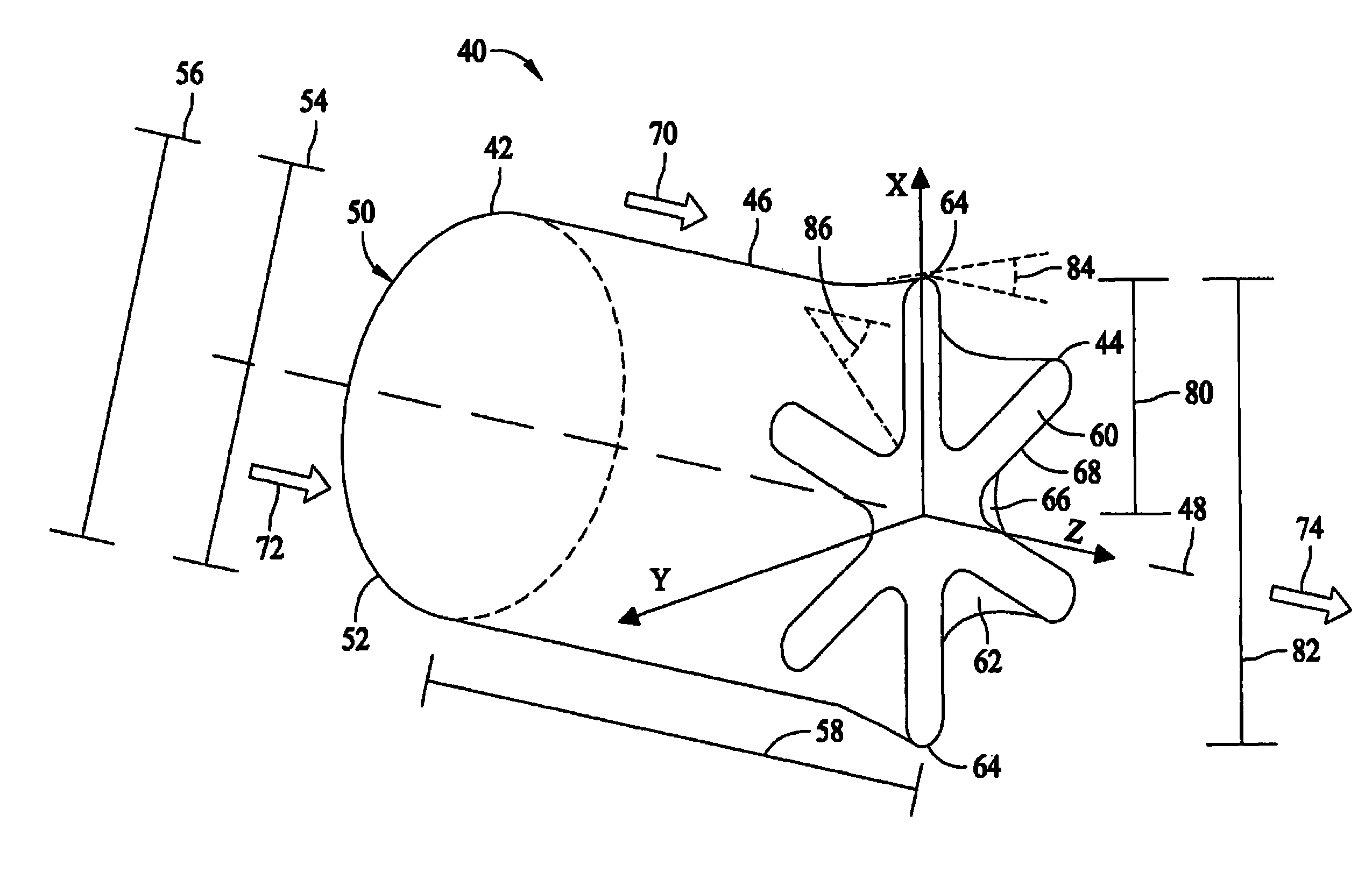
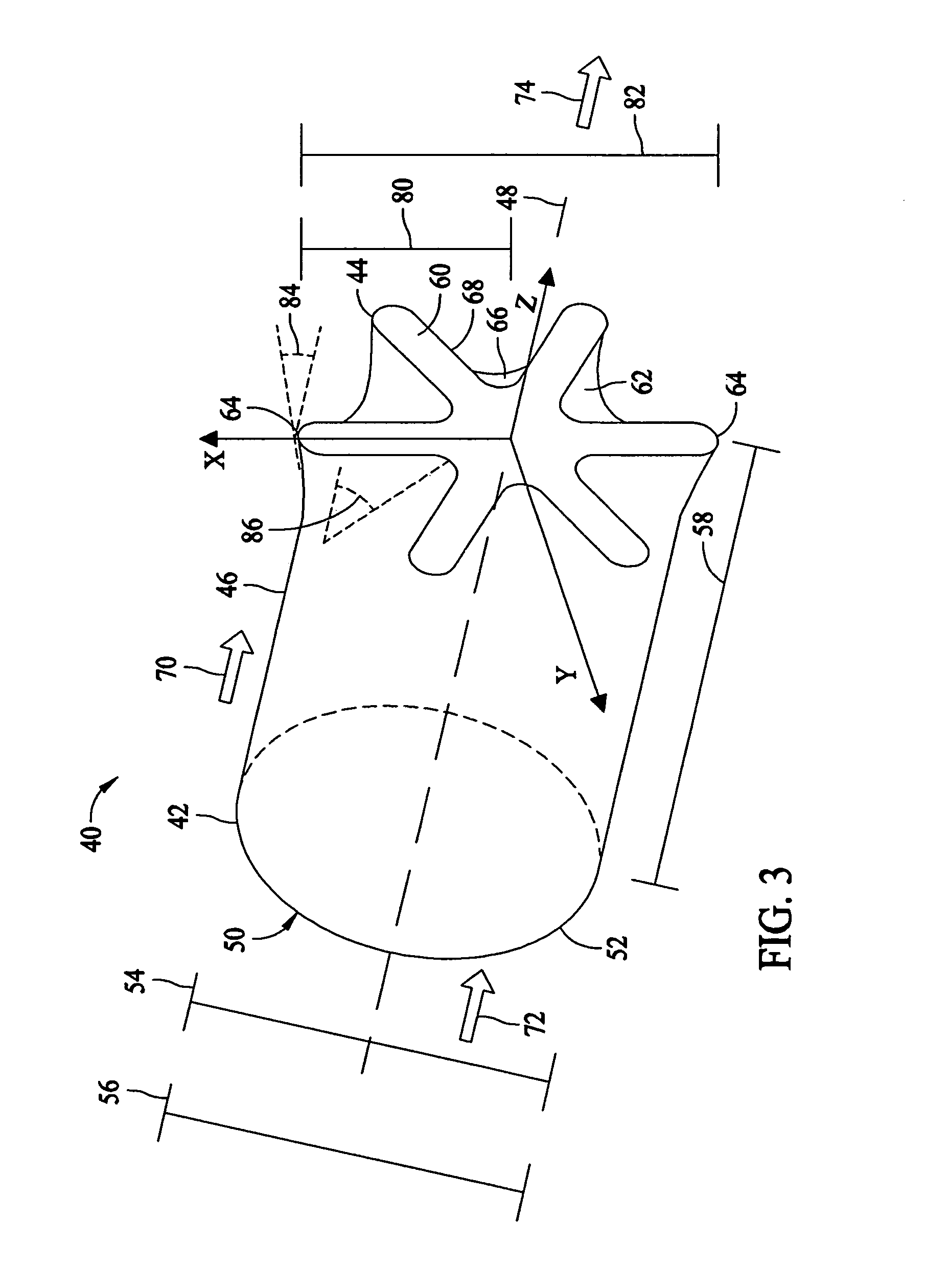
[0015...


PUM


Abstract

A method for operating a pulse detonation engine, wherein the method includes channeling air flow from a pulse detonation combustor into a flow mixer having an inlet portion, an outlet portion, and a body portion extending therebetween. The method also includes channeling ambient air past the flow mixer and mixing the air flow discharged from the pulse detonation combustor with the ambient air flow such that a combined flow is generated from the flow mixer that has less flow variations than the air flow discharged from the pulse detonation combustor.

Description

BACKGROUND OF THE INVENTION[0001]This invention relates generally to turbine engines, more particularly to methods and apparatus for operating a pulse detonation engine.[0002]Known pulse detonation engines generally operate with a detonation process having a pressure rise, as compared to engines operating within a constant pressure deflagration. As such, pulse detonation engines may have the potential to operate at higher thermodynamic efficiencies than may generally be achieved with deflagration-based engines.[0003]At least some known hybrid pulse detonation-turbine engines have replaced the steady flow constant pressure combustor within the engine with a pulse detonation combustor that may include at least one pulse detonation chamber. Although such engines vary in their implementation, a common feature amongst hybrid pulse detonation-turbine engines is that air flow from a compressor is directed into the pulse detonation chamber wherein the air is mixed with fuel and ignited to p...

Claims


Application Information

Patent Timeline
Patent Type & Authority Patents(United States)
IPC IPC(8): F02K5/02
CPCF23R7/00
Inventor RASHEED, ADAMMCMANUS, KEITH ROBERTDEAN, ANTHONY JOHN
Owner GENERAL ELECTRIC CO
Why Eureka
Try Eureka