Positive-angled light beam rotary saw cut alignment device

a light beam and rotary saw technology, applied in the direction of metal sawing devices, metal sawing accessories, manufacturing tools, etc., can solve the problems of inapplicability of most saw owners and operators, time and care, and difficulty in adjusting the cutting angle, so as to improve the safety of operation and reduce the amount of time required. , the effect of improving the accuracy and convenience of us

Inactive Publication Date: 2010-11-23
CALUORI RAYMOND J
View PDF7 Cites 0 Cited by
  • Summary
  • Abstract
  • Description
  • Claims
  • Application Information

AI Technical Summary

Benefits of technology

[0011]It is a further object of this invention to provide such a cut alignment device that decreases the amount of time required for a saw operator to align the material with the cutting edge of the saw blade.
[0012]It is a further object of this invention to provide such a cut alignment device that increases the safety of operating the saw.
[0013]This invention results from the realization that rotary saws can be made more accurate and easier to use with a light-source mounted on the rotating portion of the saw which projects a beam of light on the material to be cut.
[0014]This invention features a cut alignment device for a rotary saw having a motor which spins a cutting unit which includes a rotary shaft driven by the motor, a circular blade having a central aperture through which the shaft fits, and a blade mounting device for holding the blade on the shaft, the cut alignment device comprising a housing, a battery power source located within the housing, and a beam light source, operatively connected to the power source, and located within the housing. The light source projects a light beam from the cutting unit directed slightly away from the plane of the blade at a positive angle such that the beam is not parallel to, and is projected on a path that never intersects the plane of the blade, to assist the operator in cutting accurately.
[0016]Also featured is a cut alignment device for a rotary saw having a motor which spins a cutting unit which includes a rotary shaft driven by the motor, a circular blade having a central aperture through which the shaft fits, and a blade mounting device for holding the blade on the shaft, the cut alignment device comprising a battery power source mounted within a housing which comprises the blade mounting device, a light source operatively connected to the power source and mounted within the housing, wherein the housing defines an aperture from which the light emanates, and a centrifugally-engaged switch between the power source and the light source and mounted within the housing to automatically power the light source when the shaft is spinning, wherein the light source projects a light beam from the aperture directed slightly away from the plane of the blade at a positive angle such that the beam is not parallel to the plane of the blade and never intersects the plane of the blade, to assist the operator in cutting accurately.

Problems solved by technology

This takes time and care, but is critical for a proper cut.
These devices must be manually aligned before cutting begins, thus requiring experience and additional time.
Accordingly, devices of this nature are not practical for most saw owners and operators.

Method used


Image

  • Positive-angled light beam rotary saw cut alignment device
  • Positive-angled light beam rotary saw cut alignment device
  • Positive-angled light beam rotary saw cut alignment device

Examples


Embodiment Construction

[0034]The disclosures of the parent applications, Ser. No. 10 / 207,502 filed on Jul. 29, 2002, and Ser. No. 10 / 878,988 filed on Jun. 28, 2004, are incorporated herein by reference.

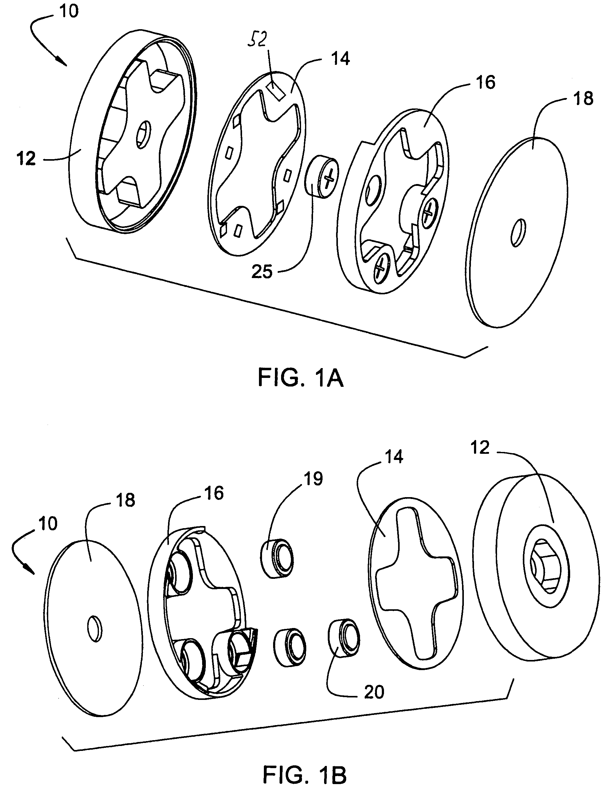
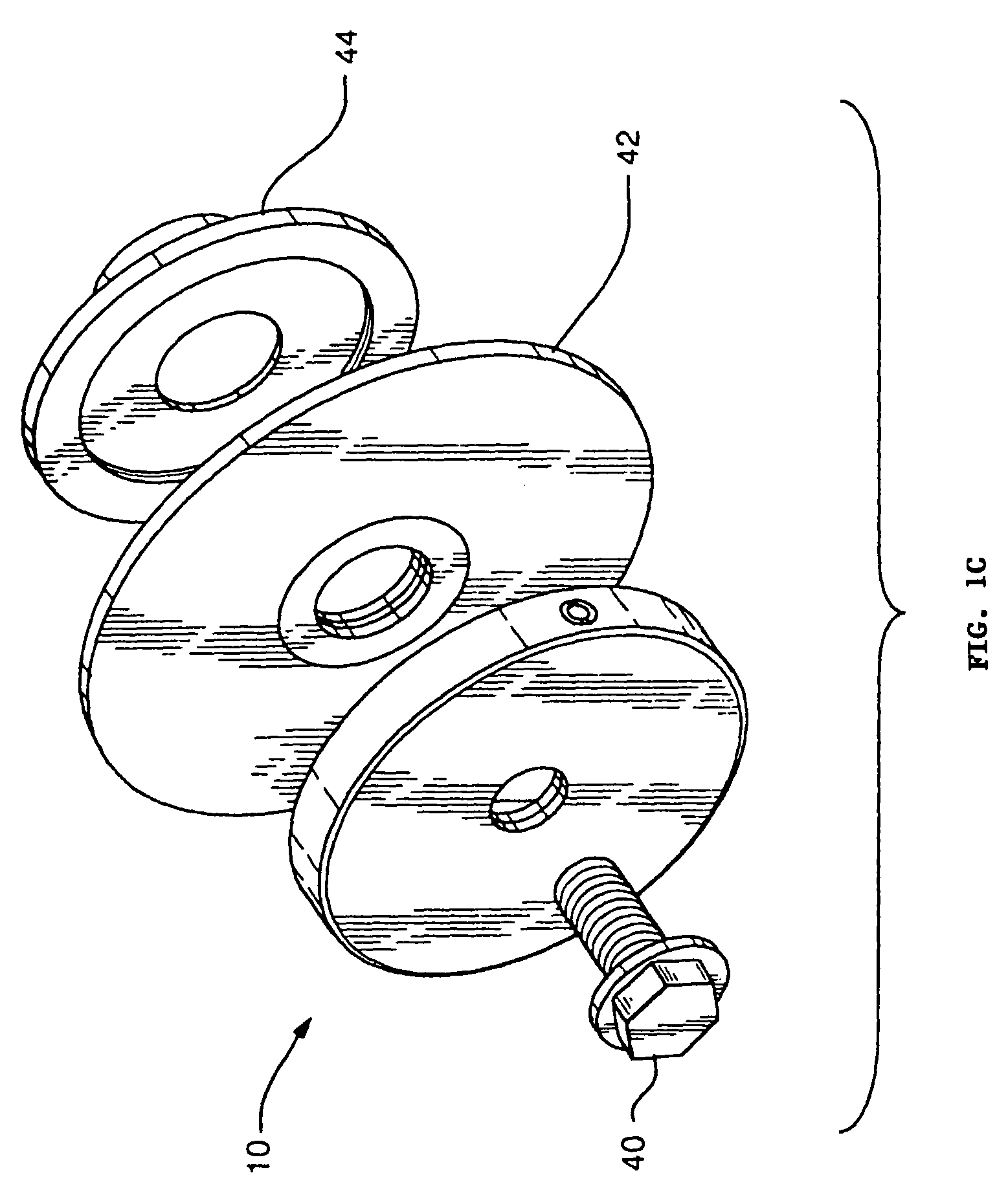
[0035]One embodiment of the inventive device is shown in FIGS. 1-6. Device 10 includes stainless steel housing 12 that provides the structural integrity for the device. The raised central cross-shaped portion 13 with four arms protects the electronic components that are located in the pockets 21-24 created thereby (not shown fully in the drawings) so that they are not crushed when the device is placed on an arbor and the nut is tightened down; it also maintains the integrity of the housing so that it doesn't bend and change the alignment of the laser beam. Also, this construction helps to maintain the device to be sufficiently mass-balanced around the center of the device, so that it is relatively rotationally balanced. Battery holder 16 is a plastic molded part that has three cavities to hold three button ...


PUM

PropertyMeasurementUnit
diameteraaaaaaaaaa
angleaaaaaaaaaa
poweraaaaaaaaaa

Abstract

A cut alignment device for a rotary saw having a motor which spins a cutting unit which includes a rotary shaft driven by the motor, a circular blade having a central aperture through which the shaft fits, and a structural housing. The cut alignment device includes the structural housing defining two or more internal compartments, a battery power source carried within the structural housing, and a beam light source, operatively connected to this power source, and also located within the structural housing. The light source projects a light beam from the cutting unit directed slightly away from the plane of the rotary cutting tool or saw blade such that it never intersects the plane of the blade, to assist the operator in cutting accurately.

Description

CROSS REFERENCE TO RELATED APPLICATION[0001]This application is a continuation-in-part of application Ser. No. 10 / 207,502 filed on Jul. 29, 2002, now U.S. Pat. No. 6,915,727 and a continuation-in-part of application Ser. No. 10 / 878,988 filed on Jun. 28, 2004. Priority of both applications is claimed.FIELD OF THE INVENTION[0002]This invention relates to a saw-mounted cut alignment device for a rotary saw which projects a line of light along the stock being cut to assist the operator in making a cut.BACKGROUND OF THE INVENTION[0003]Rotary saws such as circular saws, chop saws, radial arm saws, miter saws and table saws require that the operator properly align the material being cut with the saw blade. This takes time and care, but is critical for a proper cut.[0004]There exist laser-based cut alignment devices which are externally mounted in the vicinity of the saw, and project a light beam along the cut line. These devices must be manually aligned before cutting begins, thus requirin...

Claims


Application Information

Patent Timeline
Patent Type & Authority Patents(United States)
IPC IPC(8): B26D7/00B23D59/00
CPCB23D59/003Y10T83/7726Y10T83/839Y10T83/828Y10T83/856
Inventor CALUORI, RAYMOND J.
Owner CALUORI RAYMOND J
Why Eureka
Try Eureka