

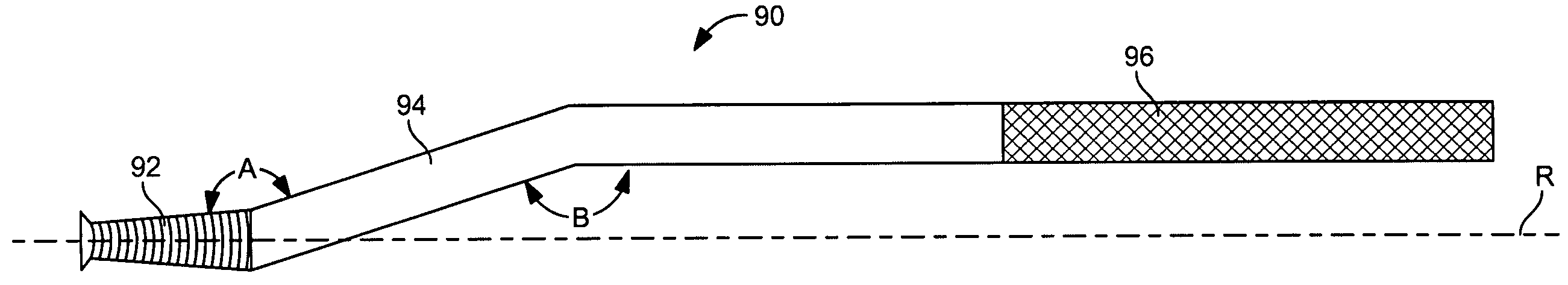
Compensating angle offset safety winch bar
a safety winch and offset technology, applied in the field of winch bars, can solve the problems of uncontrollable inability to perform the winch bar, and inability to control the spiral rotation so as to reduce the risk of the winch bar twisting, and reduce the risk of the conical rotation.
- Summary
- Abstract
- Description
- Claims
- Application Information
AI Technical Summary
Benefits of technology
Problems solved by technology
Method used
Image

Examples
Embodiment Construction
[0054]Before beginning a detailed description of the subject invention, mention of the following is in order. When appropriate, like reference materials and characters are used to designate identical, corresponding, or similar components in differing figure drawings. The figure drawings associated with this disclosure typically are not drawn with dimensional accuracy to scale, i.e., such drawings have been drafted with a focus on clarity of viewing and understanding rather than dimensional accuracy.
[0055]In the interest of clarity, not all of the routine features of the implementations described herein are shown and described. It will, of course, be appreciated that in the development of any such actual implementation, numerous implementation-specific decisions must be made in order to achieve the developer's specific goals, such as compliance with application- and business-related constraints, and that these specific goals will vary from one implementation to another and from one d...
PUM
| Property | Measurement | Unit |
|---|---|---|
| angles | aaaaa | aaaaa |
| angle | aaaaa | aaaaa |
| length | aaaaa | aaaaa |
Abstract
Description
Claims
Application Information