
Panoramic three-dimensional adapter for an optical instrument and a combination of such an adapter and such an optical instrument

a three-dimensional adapter and optical instrument technology, applied in the field of panoramic three-dimensional (3d) adapters for optical instruments and the combination of such adapters and such optical instruments, can solve the problems of large visible errors, brightness and matching errors, complex and expensive setup, etc., and achieve the effect of relatively easy manufacture of mirrors and easy operation

Inactive Publication Date: 2010-11-23
SHARP KK
View PDF15 Cites 16 Cited by
  • Summary
  • Abstract
  • Description
  • Claims
  • Application Information

AI Technical Summary

Benefits of technology

Enables simple, high-resolution capture or projection of stereoscopic images without complex processing or alignment issues, allowing for still and video recording with reduced processing requirements and no object-dependent unwrapping, using identical mirrors for easy manufacturing and integration with standard cameras or projectors.

Problems solved by technology

Such an arrangement typically provides good quality images but is complex and expensive to set up.
Also, because several cameras are used to capture the images, there may be brightness and matching errors when the panoramic stereoscopic images are constructed from the individually captured images.
Such a problem is typical of any multiple camera system, whether 2D or 3D, in which images captured by different cameras are combined together to form a composite image.
Also, because of the nature of such a rotating head camera, different vertical slices of the image are captured at different times and this may result in substantial visible errors if there is any significant movement in the scene or object whose image is being captured.
Also, the resolution of the captured images is generally relatively low.
However, such an arrangement is only capable of providing 2D image capture.
This reduces the effect caused by the camera obscuring the field of view below the mirror.
However, such an arrangement using multiple cameras 3 has the difficulties and problems of matching, synchronisation and alignment as mentioned hereinbefore.
Also, the relatively large non-symmetric mirror arrangement 1 is bulky and relatively expensive.
However, because the separation between the mirrors is vertical rather than horizontal, the disparity between the separate images is vertical and does not provide a horizontal baseline to permit horizontal stereoscopically related images to be extracted directly.
Such processing can be unreliable and may leave dark areas in the final images where there is no image data.
Also, the captured images are of different sizes and resolutions and are therefore difficult to process together without loss of resolution or loss of quality.
However, such an arrangement requires three cameras and has the problems of the optical system matching, synchronisation and alignment as mentioned hereinbefore and, again, is difficult to set up.
However, such a mirror arrangement is difficult to make and it is not possible to provide a full 360° panoramic view in a single shot.

Method used


Image

  • Panoramic three-dimensional adapter for an optical instrument and a combination of such an adapter and such an optical instrument
  • Panoramic three-dimensional adapter for an optical instrument and a combination of such an adapter and such an optical instrument
  • Panoramic three-dimensional adapter for an optical instrument and a combination of such an adapter and such an optical instrument

Examples


Embodiment Construction

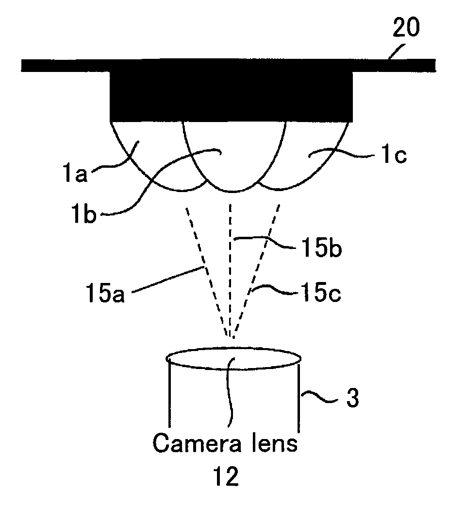
[0069]FIG. 6 illustrates the derivation of an unwrapping equation in the case of a simple known type of catadioptric camera system with a convex hyperboloid mirror 1 for a 2D panoramic camera including a conventional or standard camera 3. Such an arrangement is disclosed, for example, in “Panoramic Vision, Sensors, Theory and Applications”, Ed. Benosman and Kang, Springer, 2001.

[0070]The system comprises a convex hyperbolic mirror 1 which is axisymmetric about an axis 9 and with a first focus of the hyperbola at 10. The mirror 1 is disposed above a camera 3 comprising a lens aperture 12 and a charge-coupled device (CCD) sensor 13. The second focus of the hyperbola is located at the principal point 11 of the lens aperture 12. The camera 3 thus “sees” a reflection from the mirror 1 of a scene extending through 360° around the camera axis, which is coincident with the axis of symmetry 9, and with a vertical field dependent on the design of the mirror 1.

[0071]It is necessary that the mi...


PUM


Abstract

An adapter is provided for adapting an optical instrument, such as a camera (3) or a projector, to capture or display panoramic three-dimensional images. The adapter comprises a plurality of mirrors (1a, 1b, 1c), each of which has a reflective surface which is in the shape of a curved non-circular conic section rotated about an axis of symmetry (15a, 15b, 15c). The reflective surfaces have first foci which are spaced perpendicularly from a longitudinal axis of the adapter and which are angularly spaced around the longitudinal axis. For example, the conic section may be a hyperbola with first foci equidistantly spaced from the longitudinal axis and equiangularly spaced around 15b the longitudinal axis. The axes of symmetry (15a, 15b, 15c) of the mirrors (1a, 1b, 1c) converge to intersect the longitudinal axis at a point which is coincident with the front principal point of, for example, a camera lens (12). Thus, single shot capture of all the image data for the or each panoramic three-dimensional image may be performed.

Description

TECHNICAL FIELD[0001]The present invention relates to a panoramic three-dimensional (3D) adapter for an optical instrument and a combination of such an adapter and such an optical instrument. For example, such an optical instrument may comprise a camera which, when including or mounted to such an adapter, may be used as a stereoscopic panoramic camera. As an alternative, the optical instrument may comprise a projector which, when mounted to or including such an adapter, may be used to form a panoramic stereoscopic projection display.BACKGROUND ART[0002]There are several known types of wide field or panoramic stereoscopic cameras. A first type uses a plurality of cameras, usually a multiple of 6 cameras, disposed in a circular or spherical arrangement. Such an arrangement typically provides good quality images but is complex and expensive to set up. Also, because several cameras are used to capture the images, there may be brightness and matching errors when the panoramic stereoscopi...

Claims


Application Information

Patent Timeline
Patent Type & Authority Patents(United States)
IPC IPC(8): G02B27/14G03B35/10G03B37/00H04N13/00
CPCG03B35/10G03B37/00H04N13/0217H04N13/0459H04N13/218H04N13/363
Inventor MONTGOMERY, DAVID JAMESJONES, GRAHAM ROGER
Owner SHARP KK
Learn More