Transportation apparatus and drive mechanism

a technology of transporting apparatus and driving mechanism, which is applied in the direction of mechanical control devices, process and machine control, instruments, etc., can solve the problems of wasting time, unable to perform swift exchange operation, and unable to increase the pivot speed, so as to reduce the number of motors serving as driving sources, reduce the cost of the apparatus and the entire weight

Active Publication Date: 2010-11-23
TOKYO ELECTRON LTD
View PDF9 Cites 815 Cited by
  • Summary
  • Abstract
  • Description
  • Claims
  • Application Information

AI Technical Summary

Benefits of technology

[0014]It is another object of the present invention to provide a transfer apparatus in which the number of motors serving as a driving source can be decreased to decrease the apparatus cost and the entire weight.
[0015]It is a further object of the present invention to provide a driving mechanism which can detect a positional relationship among a plurality of driving shafts relative to each other without using an encoder or the like.

Problems solved by technology

This large pivot angle leads to a waste of time and accordingly swift exchange operation cannot be performed.
In particular, as the wafer size increases from a diameter of 200 mm to 300 mm, the wafer weight increases, so the pivot speed cannot be increased.
Thus, the extending / contracting speed of the arm 8 cannot be increased very much.

Method used


Image

  • Transportation apparatus and drive mechanism
  • Transportation apparatus and drive mechanism
  • Transportation apparatus and drive mechanism

Examples


first embodiment

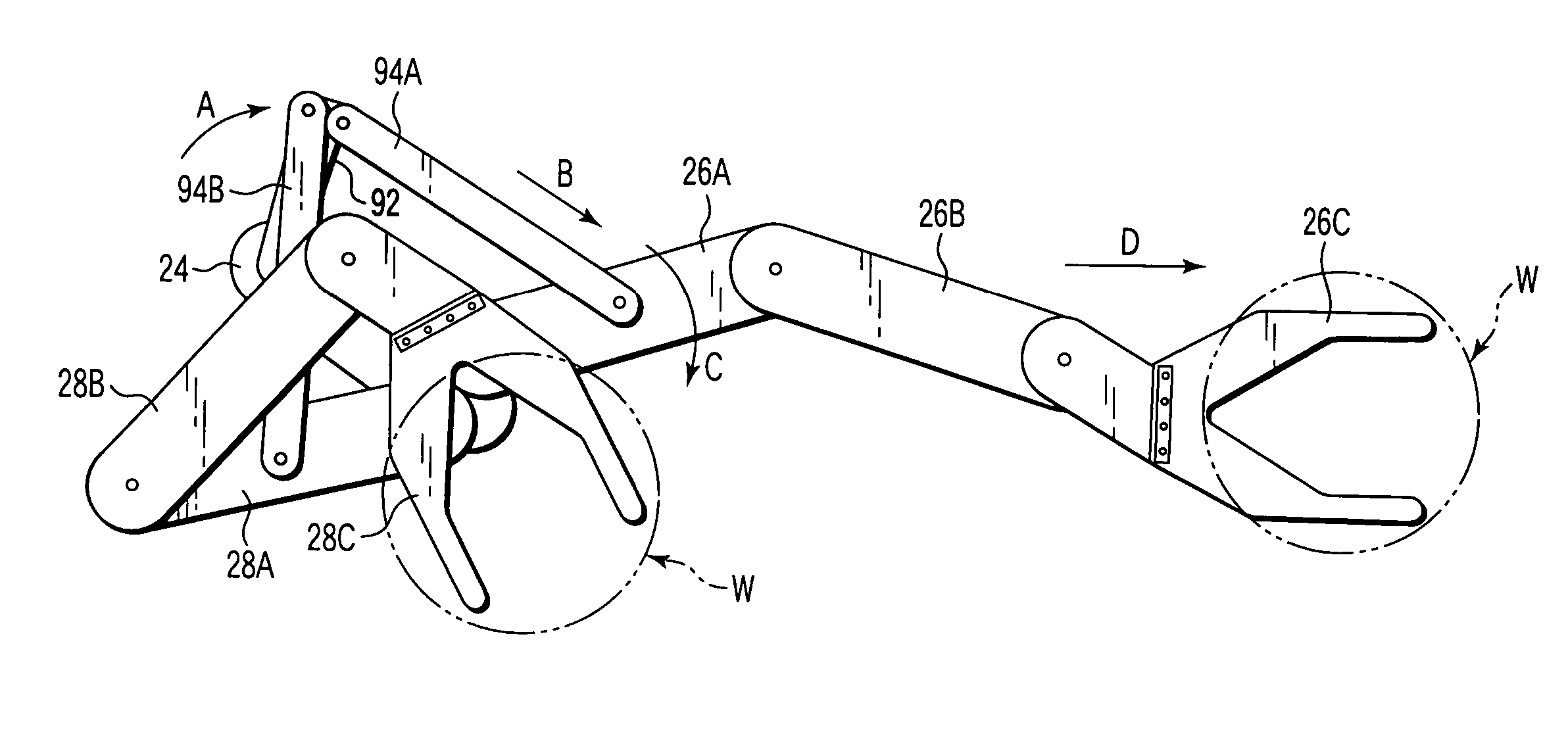
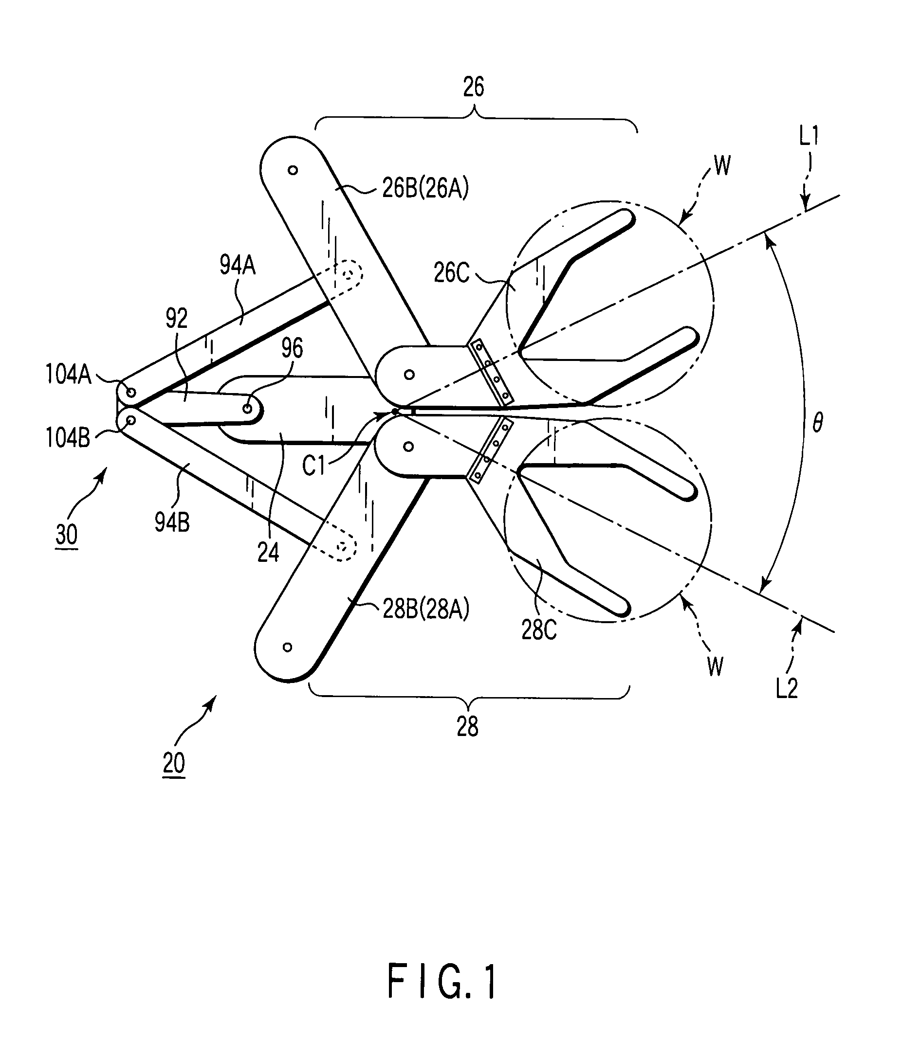
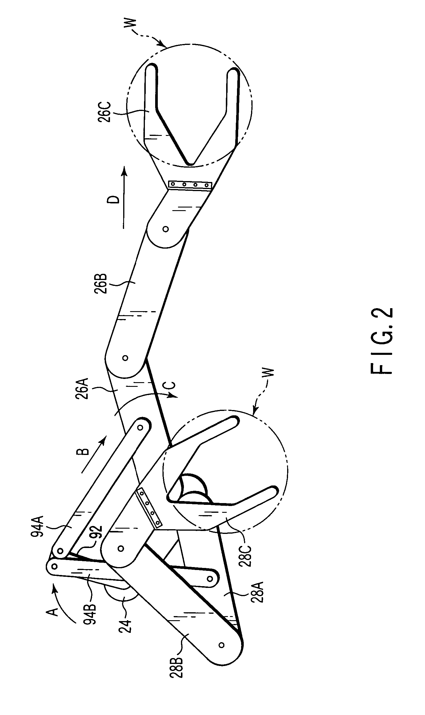
[0065]FIG. 1 is a plan view showing a state of a transfer apparatus according to a first embodiment of the present invention wherein two arm mechanisms are contracted. FIG. 3 is a sectional view showing the transfer apparatus shown in FIG. 1.

[0066]A transfer apparatus 20 incorporates a rotary base 24 rotatably supported by a base 22 (see FIG. 3). A pair of arm mechanisms, i.e., a first arm mechanism 26 and a second arm mechanism 28, are supported by the rotary base 24, so that they can pivot, bend, and stretch. A link mechanism 30 is disposed to selectively bend or stretch the first and second arm mechanisms 26 and 28. A first driving source 32 (see FIG. 3) is disposed to rotatably drive the rotary base 24. A second driving source 34 (see FIG. 3) is disposed to drive the link mechanism 30 to swingably pivot, so as to bend or stretch the first and second arm mechanisms 26 and 28.

[0067]The base 22 is formed of the bottom plate or the like of a transfer chamber which is disposed in, e....

second embodiment

[0092]FIG. 5 is a perspective view showing a state of a transfer apparatus according to a second embodiment of the present invention wherein two arm mechanisms are contracted. FIG. 6 is a plan view showing a state of the transfer apparatus shown in FIG. 5 wherein one arm mechanism is extended. FIG. 7 is a partially cutaway view showing the transfer apparatus shown in FIG. 5.

[0093]The second and first embodiments are different in the following respects. Namely, in the first embodiment, the proximal end portions of the first and second arm mechanisms 26 and 28 are supported on the rotary base 24 pivotally by two different shafts, i.e., the fixed shafts 50 and 52, respectively. In the second embodiment, the proximal end portions of first and second arm mechanisms 26 and 28 are pivotally supported by one fixed shaft. In the first embodiment, the picks 26C and 28C are arranged on one plane to face in different directions. In the second embodiment, picks 26C and 28C are overlapped vertica...

third embodiment

[0101]FIG. 9 is a plan view showing a state of a transfer apparatus according to a third embodiment of the present invention wherein two arm mechanisms are contracted. FIG. 10 is a plan view showing a state of the transfer apparatus shown in FIG. 9 wherein one arm mechanism is extended. FIG. 11 is a partially cutaway view mainly showing the link mechanism portion of the transfer apparatus shown in FIG. 9.

[0102]According to the third embodiment, in the same manner as in the second embodiment, picks 26C and 28C overlap vertically, and the proximal end portions of first and second arm mechanisms 26 and 28 are coaxial and pivotal. The third embodiment is largely different from the first and second embodiments in the following respect. Namely, the driving link 92 (see FIGS. 1 and 6) of the link mechanism 30 is replaced by a small link mechanism 112, i.e., which is small. In other words, as apparent from comparison with FIG. 4, in place of the driving link 92 shown in FIG. 4, the small li...


PUM


Abstract

A transfer apparatus (20) for a target substrate (W) includes a rotatable rotary base (24). First and second arm mechanisms (26, 28) are attached to the rotary base and configured to bend and stretch. Each of the first and second arm mechanisms has a proximal end arm (26A, 28A), an intermediate arm (26B, 28B), and a pick (26C, 28C) which are pivotally coupled to each other sequentially from the rotary base. The picks are disposed to support the target substrate. A link mechanism (30) is coupled to the proximal end arms of the first and second arm mechanisms to drive the first and second arm mechanisms. A first driving source (32) is disposed to rotatably drive the rotary base. A second driving source (34) is disposed to drive the link mechanism so as to bend or stretch the first and second arm mechanisms.

Description

TECHNICAL FIELD[0001]The present invention relates to a transfer apparatus and driving mechanism and, more particularly, to a transfer apparatus and driving mechanism which are used in a semiconductor processing system. Semiconductor processes refer to various types of processes performed to form a semiconductor layer, insulating layer, conductive layer, and the like on a target substrate such as a wafer or a glass substrate, e.g., an LCD (Liquid crystal display) or FPD (Flat Panel Display) with a predetermined pattern to manufacture on the target substrate a semiconductor device or a structure including a wiring, electrode, and the like to be connected to the semiconductor device.BACKGROUND ART[0002]In the semiconductor processing system which manufactures a semiconductor device and the like, the target substrate such as a semiconductor wafer is transferred. For example, the wafer is transferred through a clean atmosphere under atmospheric pressure or vacuum pressure and loaded int...

Claims


Application Information

Patent Timeline
Patent Type & Authority Patents(United States)
IPC IPC(8): B25J18/02B25J9/04B25J9/10H01L21/687
CPCB25J9/042B25J9/107H01L21/68707H01L21/67742Y10T74/20305B25J9/06B25J13/08H01L21/68
Inventor SAEKI, HIROAKIISHIZAWA, SHIGERUSHINDO, TAKEHIROHIROKI, TSUTOMUMACHIYAMA, WATARU
Owner TOKYO ELECTRON LTD
Why Eureka
Try Eureka