Swing device having circuit for generating repulsive force

a technology of generating repulsive force and swing device, which is applied in the direction of amusements, sofas, beds, etc., can solve the problems of large power consumption, complex structure, and generated operation noise, and achieve the effect of reducing the manufacturing cost of products and simplifying the construction of circuits

Inactive Publication Date: 2010-11-23
KUKUTOYS
View PDF12 Cites 26 Cited by
  • Summary
  • Abstract
  • Description
  • Claims
  • Application Information

AI Technical Summary

Benefits of technology

[0009]Accordingly, the present invention has been made to solve the above-mentioned problems occurring in the prior art, and an object of the present invention is to provide a swing device having a circuit for generating a repulsive force, capable of securing an electromagnetic driving type having no possibility of malfunction.
[0010]Another object of the present invention is to provide a swing device having a circuit for generating a repulsive force to detect the approaching of a permanent magnet and to repel the corresponding permanent magnet at the same time, using a single element, so that the construction of the circuit becomes simplified and manufacturing cost of products is thus reduced.
[0011]Still another object of the present invention is to provide a swing device having a circuit for generating a repulsive force to detect the approaching of a permanent magnet and to repel the corresponding permanent magnet at the same time, through generating induced current using a single coil when the permanent magnet passes by, so that a sensor separately provided in the past is removed to thus reduce the possibility to cause the malfunction of the circuit to detect a wrong position of a swinging object.Technical Solution

Problems solved by technology

The electric type swing device between them has a problem in that since it operates by a motor, operational noise is generated and power consumption is large.
However, such electromagnetic type swing device has the problems in that if the photo sensor detects wrong positions of the seat, the polarity of the electromagnet adjacent to the permanent magnet is changed reversely to that of the permanent magnet to cause a malfunction such as stopping the seat at that position, as well as the structure thereof is complex.

Method used


Image

  • Swing device having circuit for generating repulsive force
  • Swing device having circuit for generating repulsive force
  • Swing device having circuit for generating repulsive force

Examples


Embodiment Construction

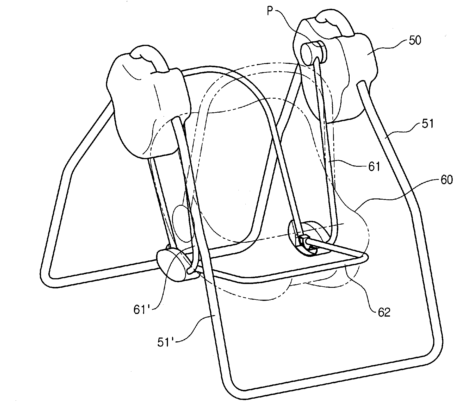
[0023]A swing device according to the present invention is configured to generate induced current when a permanent magnet passes by, using a single coil, to detect approaching of the permanent magnet, and to switch power to the corresponding coil to repel the corresponding permanent magnet as well. Hereinafter, preferred embodiments of the present invention will be described with reference to the accompanying drawings.

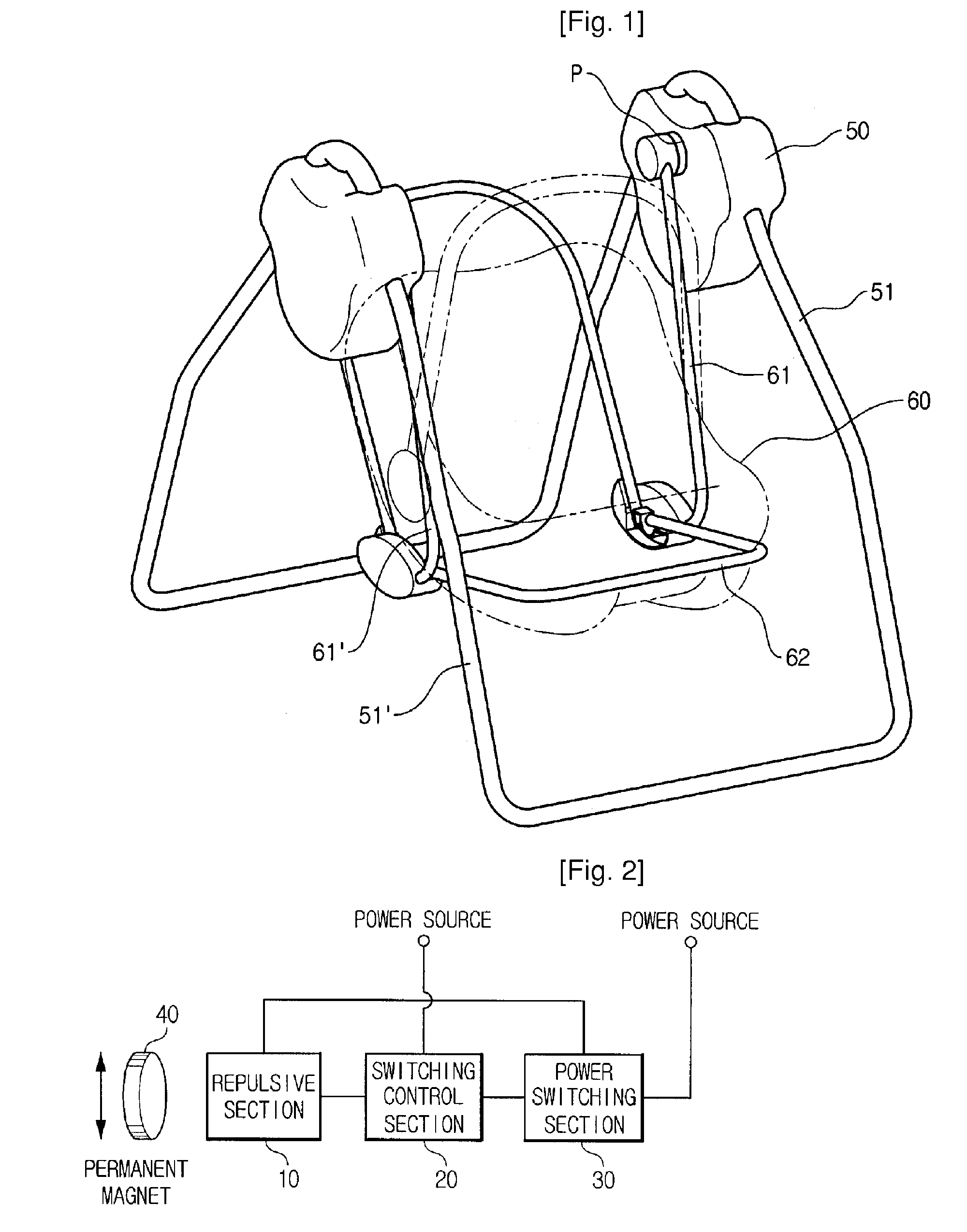
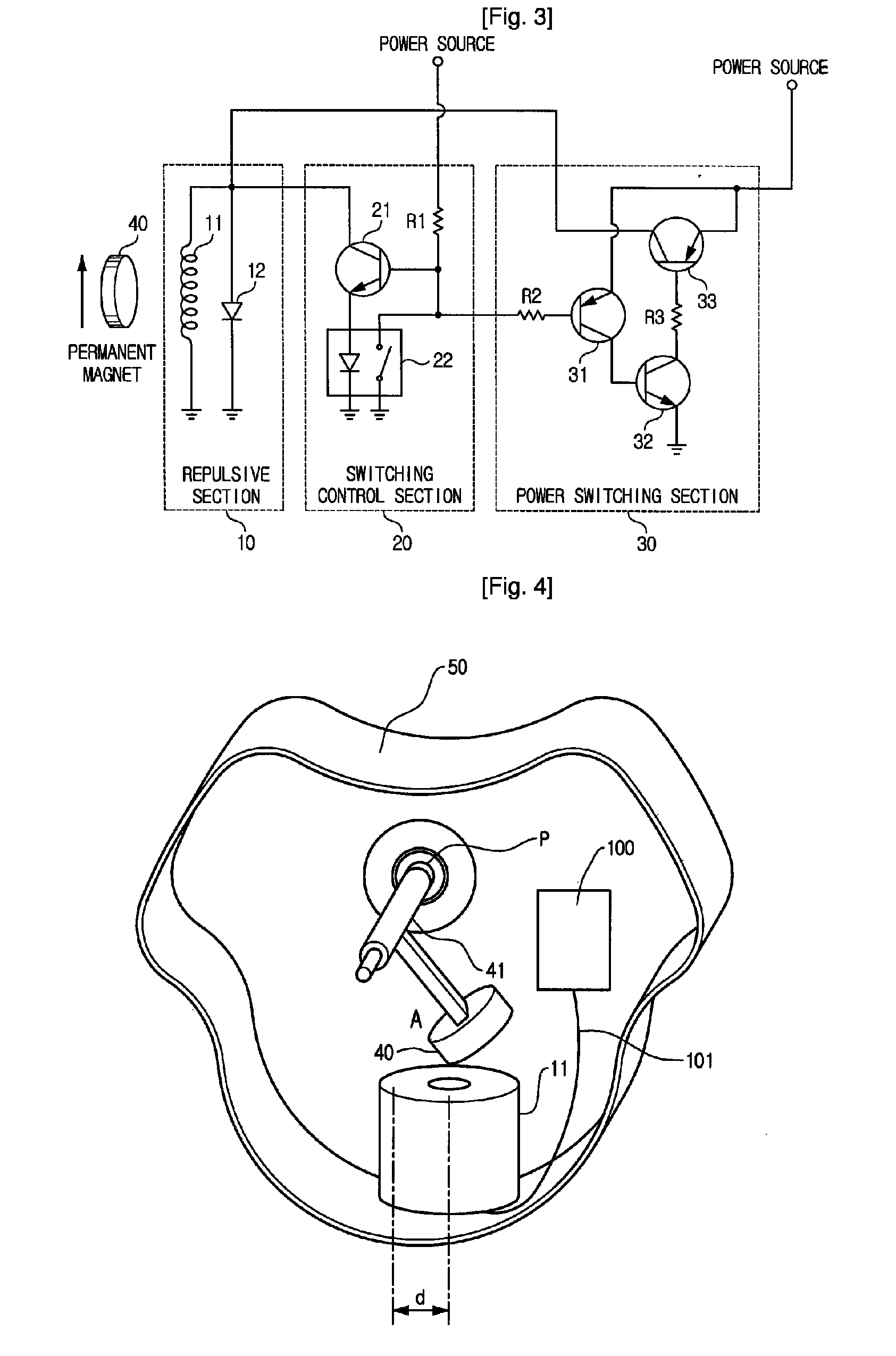
[0024]A circuit for generating a repulsive force (also referred to as a repulsive circuit) according to an embodiment of the present invention, as shown in FIG. 2, includes a repulsive force generating section 10 (also referred to as a repulsive section), a switching control section 20, and a power switching section 30. Herein, the power supplied to the switching control section 20 and the power switching section 30 is power applied from a battery or other power supply device. A permanent magnet 40 spaced to a certain distance from the corresponding repulsive section 1...


PUM


Abstract

A swing device has a support frame, a seat having a swing axis and swing back and forth about the swing axis while a bar thereof being hung on the support frame, and a repulsive circuit for repelling a permanent magnet installed on the swing axis. The repulsive circuit has a coil assembly instantly generating induced current when the permanent magnet passes by with a certain distance therebetween, and being supplied with power to become an electromagnet having the same polarity as the permanent magnet to instantly repel the permanent magnet, a first switching element for switching the induced current generated in the coil assembly, a second switching element switched on by the induced current switched from the first switching element to turn off the switching operation of the first switching element and to control a power switching operation at the same time, and a power switching unit for temporarily switching the power to the coil assembly according to the control of the power switching operation of the second switching element. According to the swing device, the construction of the circuit becomes simplified, manufacturing cost of products is reduced, and the possibility to cause the malfunction of the circuit is reduced.

Description

TECHNICAL FIELD[0001]The present invention relates to a swing device having a circuit for generating a repulsive force, and more particularly to a swing device for an infant, such as a swing or a cradle, having a circuit for generating a repulsive force, which allows to automatically swing using an electromagnetic force.BACKGROUND ART[0002]In general, a swing device for an infant has being operated such that it is swung back and forth at a regular time and interval, allowing an infant to get comfortable sleep or to play it. Although in the past, such swing device had been manually swung by the protector of an infant, recently, in order to dispense with such trouble, it has being developed an automatic swing device, which is automatically swung using external power.[0003]Such automatic swing device may be divided by the drive mechanism into an electric type in which a rotational shaft of a cradle or a swing is directly driven by a motor, and an electromagnetic type in which a cradle ...

Claims


Application Information

Patent Timeline
Patent Type & Authority Patents(United States)
IPC IPC(8): A63G9/16A63G9/00
CPCA47D13/105A63G13/00A63G9/00
Inventor KWON, YOUNG-HAN
Owner KUKUTOYS
Why Eureka
Try Eureka