Device for distributed maximum power tracking for solar arrays

a solar array and maximum power technology, applied in the field of solar cell technology, can solve the problems of limited surface area, failure to collect all the available electrical power from solar cells, and cells in an array may be subjected to variable light levels

Active Publication Date: 2010-11-23
NEWLIGHT CAPITAL LLC
View PDF8 Cites 218 Cited by
  • Summary
  • Abstract
  • Description
  • Claims
  • Application Information

AI Technical Summary

Problems solved by technology

Direct connection in series or parallel results in failure to collect all the available electrical power from the solar cells in the array and at least some of the cells will operate at a condition other than at their maximum power points.
However there are a number of problems or disadvantages associated with the use of a single maximum power device to control the voltage or current of an array or sub-array of solar cells.
Where solar cells are used to power vehicles, the vehicles are usually aerodynamically designed with curved surfaces and also have limited surface area in which to mount the solar cells.
Furthermore, cells in an array may be subjected to variable light levels due to shadowing by foreign objects such as trees and buildings between the cell and the source of illumination.
These mechanisms however may not provide uniform cooling to all cells.
As well these variations are not predictable.

Method used


Image

  • Device for distributed maximum power tracking for solar arrays
  • Device for distributed maximum power tracking for solar arrays
  • Device for distributed maximum power tracking for solar arrays

Examples


Embodiment Construction

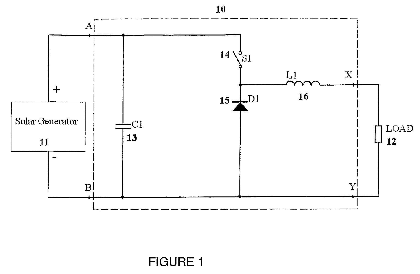
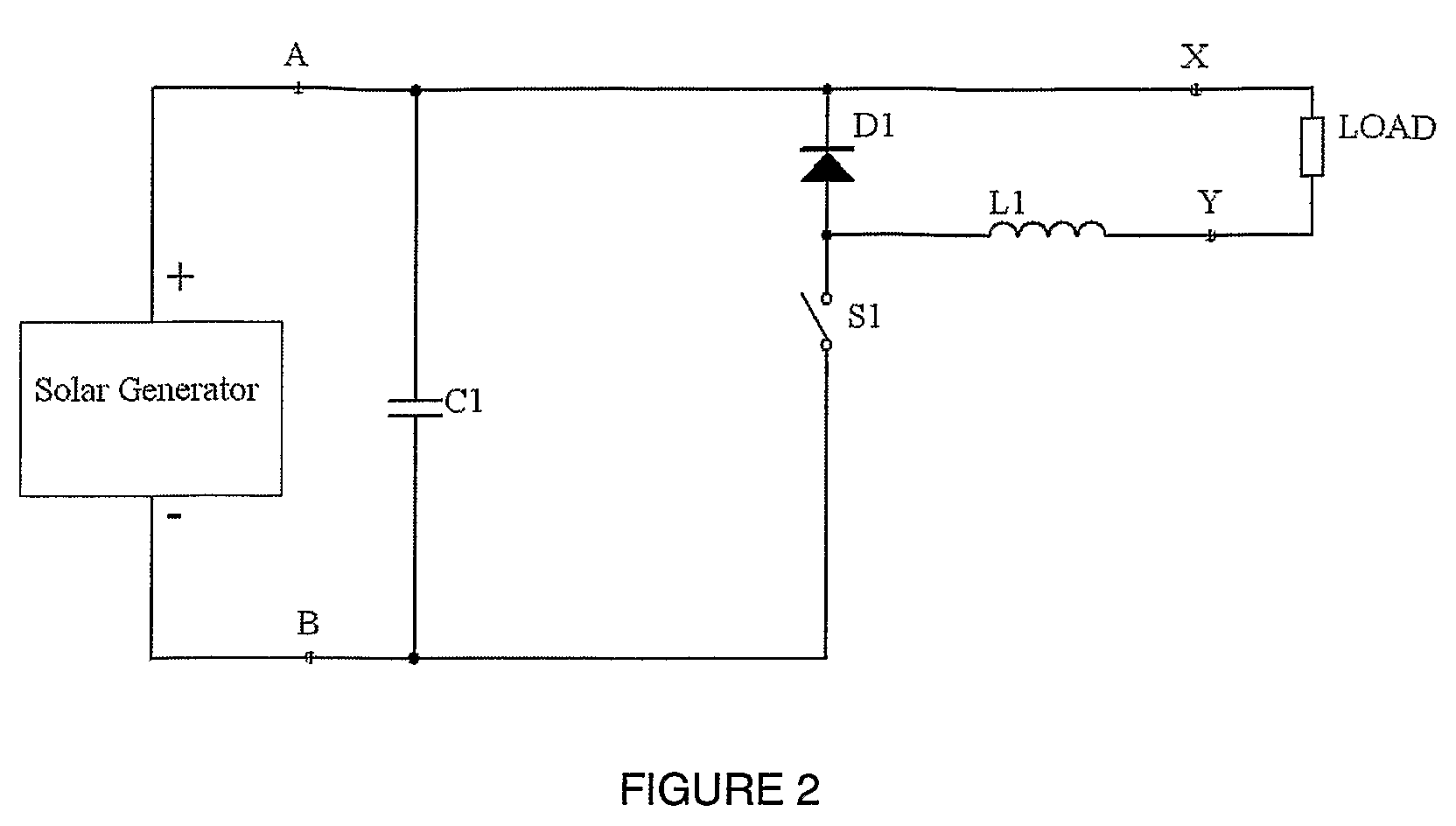
[0037]With reference to FIG. 1 there is shown a simplified buck type DC / DC converter 10 connected to a solar generator 11 and load 12. The solar generator 11 can be a solar cell or several cells. The buck type DC / DC converter 10 includes a capacitor 13 which serves as an energy storage element, a controlled switching device 14, a diode or a controlled device acting as a synchronous rectifier 15 and an output inductor 16. An alternative arrangement for the buck type DC / DC converter 10 is shown in FIG. 2.

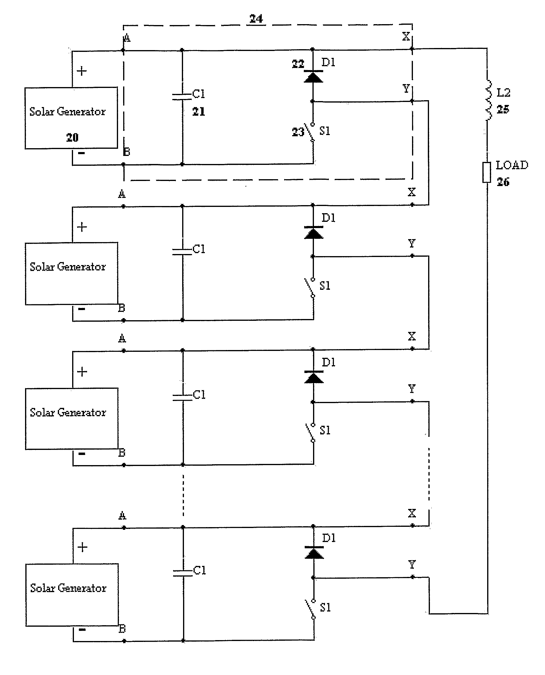
[0038]A buck type DC / DC converter can be controlled to operate the solar generator at its maximum power point while producing an adjustable level of output current. The solar generator and maximum power tracker will be referred to as a solar generator / MPPT. Many solar generators / MPPT can be series connected. Each DC / DC converter will then have an identical output current but they can be individually controlled to allow each solar generator to operate at their maximum power point.

[0039...


PUM


Abstract

A system for providing power from solar cells where each cell or cell array is allowed to produce its maximum available power and converted by its own DC / DC converter. In one form the system includes: one or more solar generators, each of which has at least one solar cell; a maximum power tracker operatively associated with each solar generator, where the maximum power tracker includes a buck type DC / DC converter without an output inductor, and the maximum power trackers of the solar generators are operatively connected in series with each other; and an inductor operatively connected to the series connected maximum power trackers.

Description

FIELD OF INVENTION[0001]The present invention relates to solar cell technology and in particular to maximum power tracking converters. The present invention has particular but not exclusive application for use in vehicles that are at least in part electrically powered by solar cells. Reference to solar powered vehicles is by means of example only and the present invention has application in other areas.BACKGROUND OF THE INVENTION[0002]A solar cell is a device able to convert incident light to electrical power. Many solar cells are typically grouped to form an array of solar cells. To collect the electrical power from the solar cells, groups of cells are either directly connected in series or in parallel. Where the cells are connected in series, they must have identical currents but if the cells are connected in parallel they must operate with identical voltages. An individual cell will produce maximum power at a unique cell voltage and current which will vary from cell to cell. The ...

Claims


Application Information

Patent Timeline
Patent Type & Authority Patents(United States)
IPC IPC(8): H02J1/00
CPCG05F1/67H02J7/35Y10S323/906Y02E10/58Y02E10/566H02M3/158G05F5/00Y02E10/56H02M1/0077H02J7/345
Inventor WOLFS, PETER
Owner NEWLIGHT CAPITAL LLC
Why Eureka
Try Eureka