Drive device

a technology of a drive device and a torsional rigidity, which is applied in the direction of mechanical energy handling, mechanical apparatus, and gearing, etc., can solve the problems of relatively high torque and high torsional rigidity, and achieve the effect of high torsional rigidity and easy manufacturing

Inactive Publication Date: 2010-11-30
SIEMENS AG
View PDF20 Cites 7 Cited by
  • Summary
  • Abstract
  • Description
  • Claims
  • Application Information

AI Technical Summary

Benefits of technology

[0010]The object of the present invention is to further develop a drive device of the aforementioned type so that it is easier to manufacture from a production engineering standpoint and so that a high torsional rigidity can be achieved.

Problems solved by technology

Secondly the drive shaft can now be connected directly to the rotor of the second drive, which makes it possible to transmit relatively high torques and leads to a high torsional rigidity.

Method used


Image

  • Drive device
  • Drive device
  • Drive device

Examples


Embodiment Construction

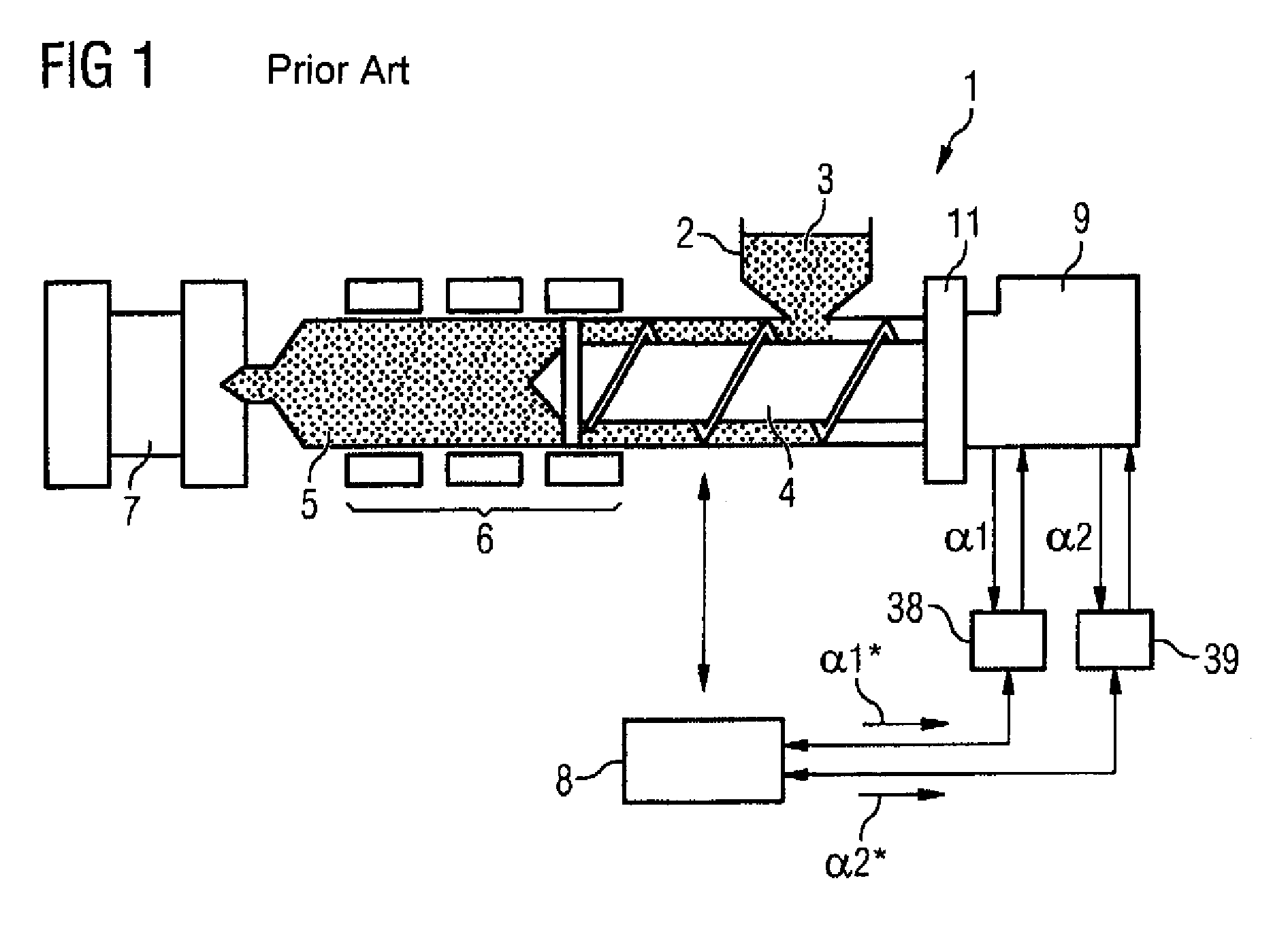
[0035]According to FIG. 1 an injection molding machine, generally denoted by the reference numeral 1, has among other things a filling hopper 2, via which plastic granulate 3 is fed to the injection molding machine 1. The plastic granulate 3 is conveyed by the rotation of a feed screw 4 into a plasticating chamber 5 of the injection molding machine 1. There it is melted through heating by means of a schematically indicated heating 6. It is then injected through axial displacement of the feed screw 4 into an injection mold 7, where it solidifies to the finished injection molded part.

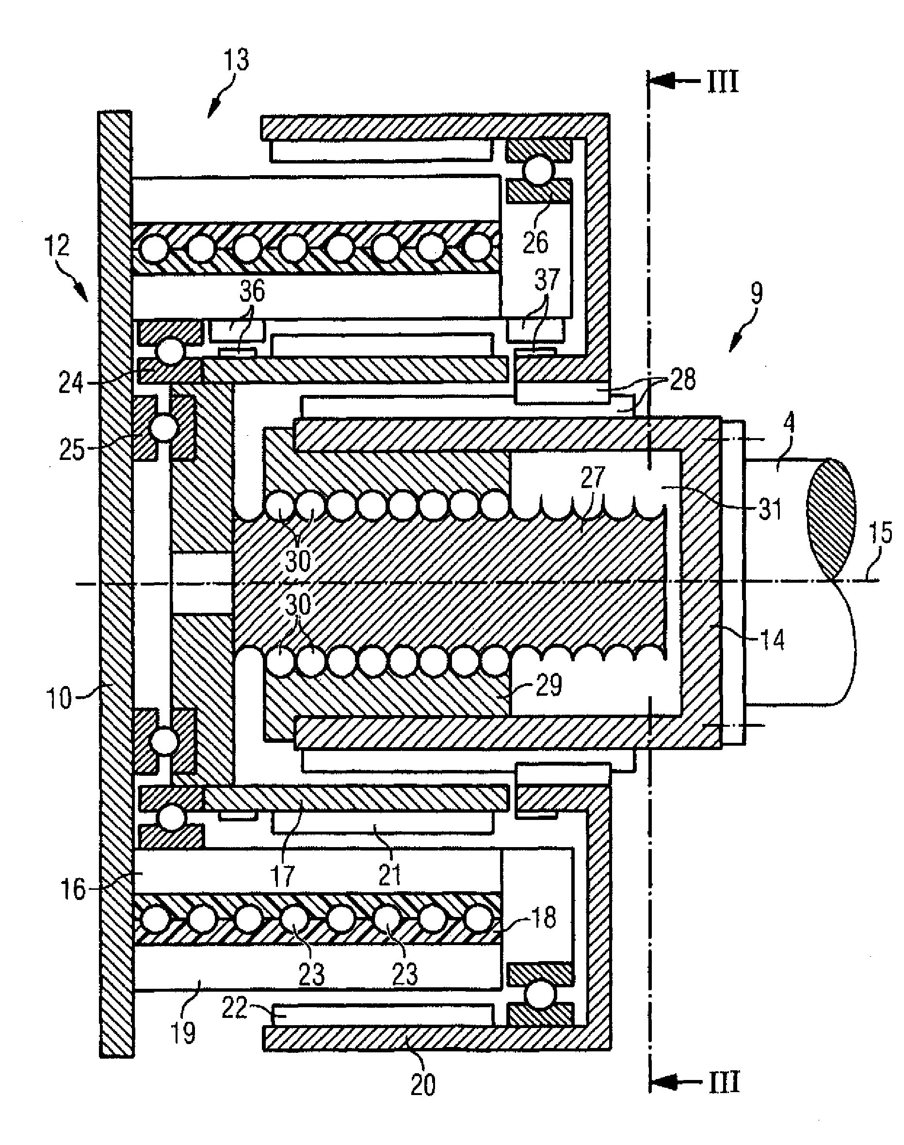
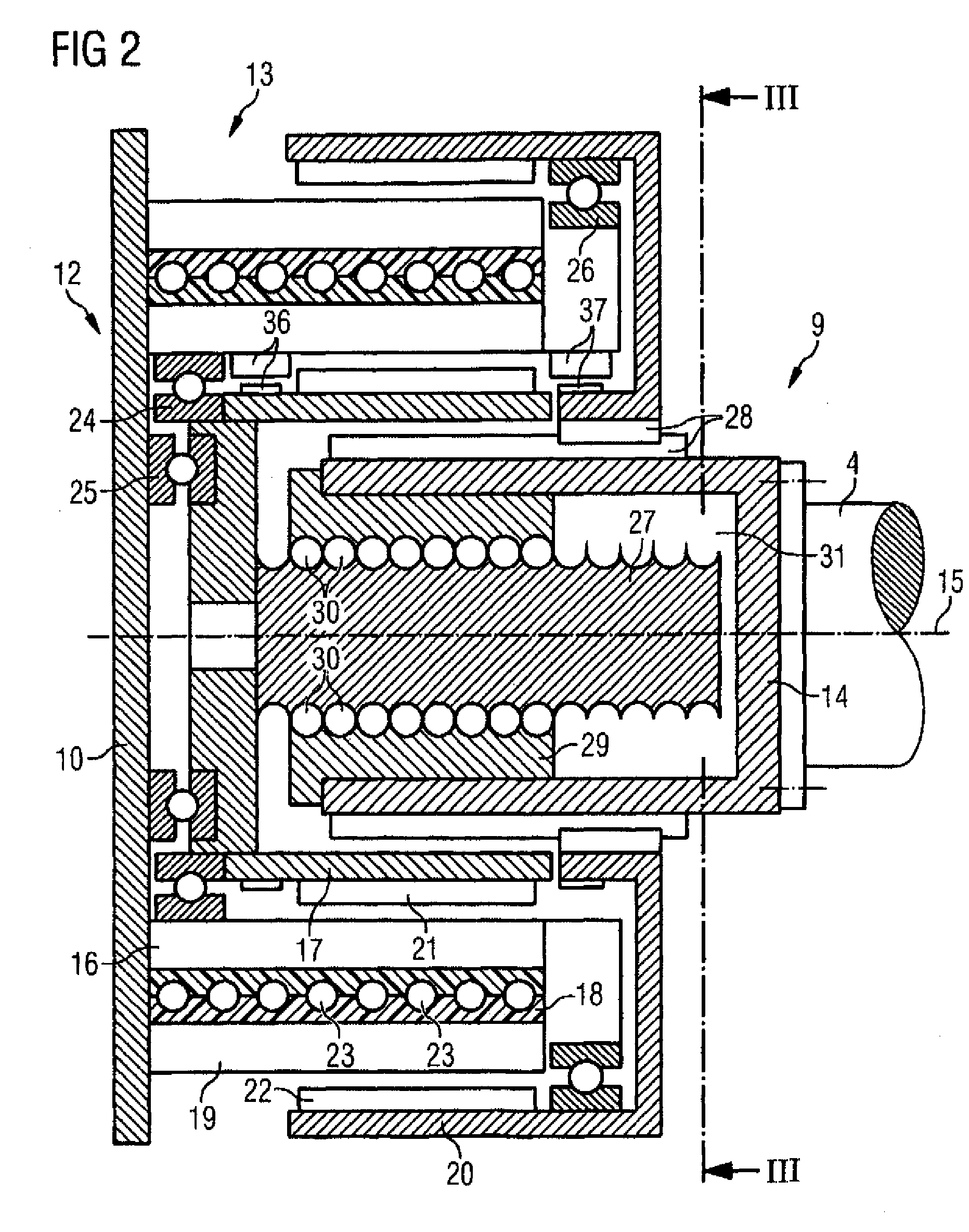
[0036]The functioning of the injection molding machine 1 is controlled by a control device 8. Among other things the control device 8 controls a drive device 9, which produces both the rotation of the feed screw 4 and the axial displacement of the feed screw 4. This drive device 9 forms the subject of the present invention. It will be explained in more detail below in conjunction with FIGS. 2 to 4, in par...


PUM

PropertyMeasurementUnit
movementsaaaaaaaaaa
torsional rigidityaaaaaaaaaa
axial lengthaaaaaaaaaa

Abstract

The invention relates to a drive device (9) comprising a housing (10), a drive shaft (14) which is mounted in the housing (10) and which comprises a shaft axis (15) and a first and a second electric drive (12,13). The drive shaft (14) can be rotated about the shaft axis (15) by means of a drive (12,13) and can be displaced in an axial manner along the shaft axis (15). The drives (12, 13) are aligned on the shaft axis (15) and comprise, respectively, a stator (16,19) and a rotor (17,20). The stators (16,19) are secured to the housing (10). The rotors (17,20) are embodied as hollow shafts and are mounted on the housing (10). The rotor (20) of the second drive (13) is rotationally secured to the drive shaft (14) by means of a linear bearing device (28), and in a manner which enables it to be axially displaced. The rotor (17) of the first drive (12) is rotationally secured to a threaded spindle (27) and is connected in such a manner that it cannot be axially displaced. Said drive shaft (14) is rotationally connected to a threaded nut (29) which co-operates with the threaded spindle (27) and in such a manner that it cannot be axially displaced. The drive shaft (14) comprises a recess (31) which is used to receive the threaded spindle (27).

Description

BACKGROUND OF THE INVENTION[0001]The present invention relates to a drive device comprising a housing, a drive shaft which is supported in the housing and which comprises a shaft axis and a first and second electric drive,[0002]the drive shaft being rotatable about the shaft axis by means of the electric drives and being axially displaceable along the shaft axis,[0003]the two drives being aligned on the shaft axis and each comprising a stator and a rotor,[0004]the stators being fixed to the housing,[0005]the rotors being embodied as hollow shafts and being supported on the housing,[0006]the rotor of the second drive being rotationally locked to the drive shaft by means of a linear bearing device, but being axially displaceable.[0007]Such a drive device is disclosed, for example, by DE 43 44 335 C2. It is used where a drive shaft is intended to be both rotatable about its shaft axis and displaceable in the direction of its shaft axis. An example of such a use is the movement of a fee...

Claims


Application Information

Patent Timeline
Patent Type & Authority Patents(United States)
IPC IPC(8): F16H27/02B29C45/50H02K7/06H02K16/02
CPCB29C45/5008H02K7/06H02K16/02Y10T74/18056Y10T74/18576
Inventor EBERLEIN, WERNERRECKER, KLAUS
Owner SIEMENS AG
Why Eureka
Try Eureka