Gas exchange valve actuator for a valve-controlled internal combustion engine

a technology of internal combustion engine and actuator, which is applied in the direction of valve operating means/release devices, machines/engines, non-mechanical valves, etc., can solve the problems of low rotor inert mass and high stability

Inactive Publication Date: 2010-11-30
COMPACT DYNAMICS
View PDF44 Cites 5 Cited by
  • Summary
  • Abstract
  • Description
  • Claims
  • Application Information

AI Technical Summary

Benefits of technology

[0020]Another concept which underlies the invention consists in “separating out” that part of the stator which brings about the circulation through the armature, namely the coil region with the stator coil arrangement, spatially from that part which forms the power of the linear motor, namely the tooth region of the stator. By this means it is possible to achieve a considerably higher circulation through the armature, compared to conventional linear motors in which the stator coils are arranged between two teeth, in each case, on the stator. This is due to the fact that, because of the design according to the invention, the coil has considerably fewer spatial limitations and can thus be optimised to minimal (ohmic) losses—and an accompanying maximum magnetic field induction. The arrangement of the stator coil arrangement, whose central longitudinal axis is oriented transversely to the direction of movement of the rotor or, in other words, is essentially in alignment with the central longitudinal axis of two mutually opposed teeth belonging to a pair of teeth, is particularly efficient magnetically, since the magnetic flux induced by a coil oriented in this way flows equally through the pairs of teeth located at both end faces of the coil. An identical force is thereby generated in both stacks of permanently magnetic bars. This avoids oblique running of the rotor without any other special measures.
[0023]The rotor magnet pole / stator tooth arrangements which give rise to force or movement are likewise concentrated, so that they are not interrupted by stator coil arrangements. This permits a very small pole pitch which, in turn, brings about a high force density. Moreover, with the arrangement according to the invention, partial strokes of the valve member are possible. It might thereby be possible, in the case of an internal combustion engine equipped with the gas is exchange valve actuators according to the invention, to dispense with a conventional throttle valve in the metering system for the fuel / air mixture and its appertaining activating system.
[0024]Another essential advantage of the gas exchange valve drive according to the invention consists in the fact that it is practically only the magnetically active components (the permanent magnets) which contribute to the inert mass of the rotor, while all the other parts of the motor (coils, magnetic short circuit, etc.) are allocated to the stator. It is thereby possible to achieve a particularly high ratio of force exerted by the actuator to inert mass. Moreover, the gas exchange valve drive according to the invention is pre-eminently suitable for use in internal combustion engines which run at high speeds. Under these circumstances, it is possible, in particular, for the approach of the valve member to the end positions (open and closed positions of the gas exchange valve) at high speed to take place with high changes in acceleration, so that the valve member impinges at minimal speed at the valve seat, whereas said valve member is otherwise moved at very high speeds. Moreover, the maximum force is available in the end regions of the path of motion. This permits operation of the gas exchange valves which is very low in noise and in wear and is, at same time, very reliable on account of the high stopping forces that can be achieved in the end positions.
[0025]Because of the arrangement, which can be very simple in design (a single-phase and hollow-cylindrical arrangement of, for example, rectangular cross-section), of the stator coil arrangements, it is possible to keep the influence of the jarring forces acting upon the coil very low, so that vibrations in the coil, or friction of the latter against the wall of the stator coil chamber, are low. It is thereby possible to manage with minimal material for insulating or lining the stator coil chamber. This also contributes to the compactness and reliability of the arrangement as a whole. Moreover, the simple construction brings about a high power density, even in the case of small gas exchange valves, since the achievable filling factor of the stator coil chamber (coil volume in said stator coil chamber, referred to the overall volume of the latter) is high.
[0035]Two adjacent permanently magnetic bars, in each case, in the two stacks on the rotor may, according to the invention, be connected to one another at a predetermined distance by magnetically inactive spacers. These spacers may contain a light, magnetically inactive material (aluminium, titanium, plastic—including plastic with glass fibre or carbon fibre inclusions—or the like). As a result, the inert mass of the rotor is low, but its stability high.
[0042]Because of the high power density of the arrangement according to the invention, the transverse dimensions of the gas exchange valve having the necessary power data can be kept very small. This permits its use in compact motor car engines.

Problems solved by technology

As a result, the inert mass of the rotor is low, but its stability high.

Method used


Image

  • Gas exchange valve actuator for a valve-controlled internal combustion engine
  • Gas exchange valve actuator for a valve-controlled internal combustion engine
  • Gas exchange valve actuator for a valve-controlled internal combustion engine

Examples


Embodiment Construction

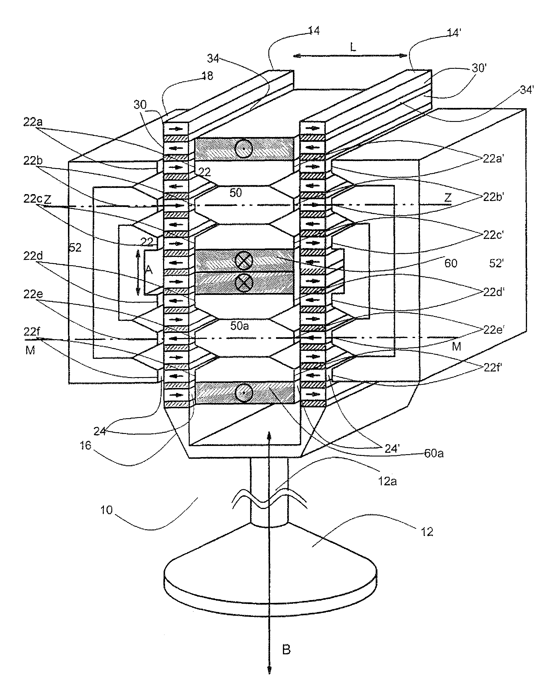
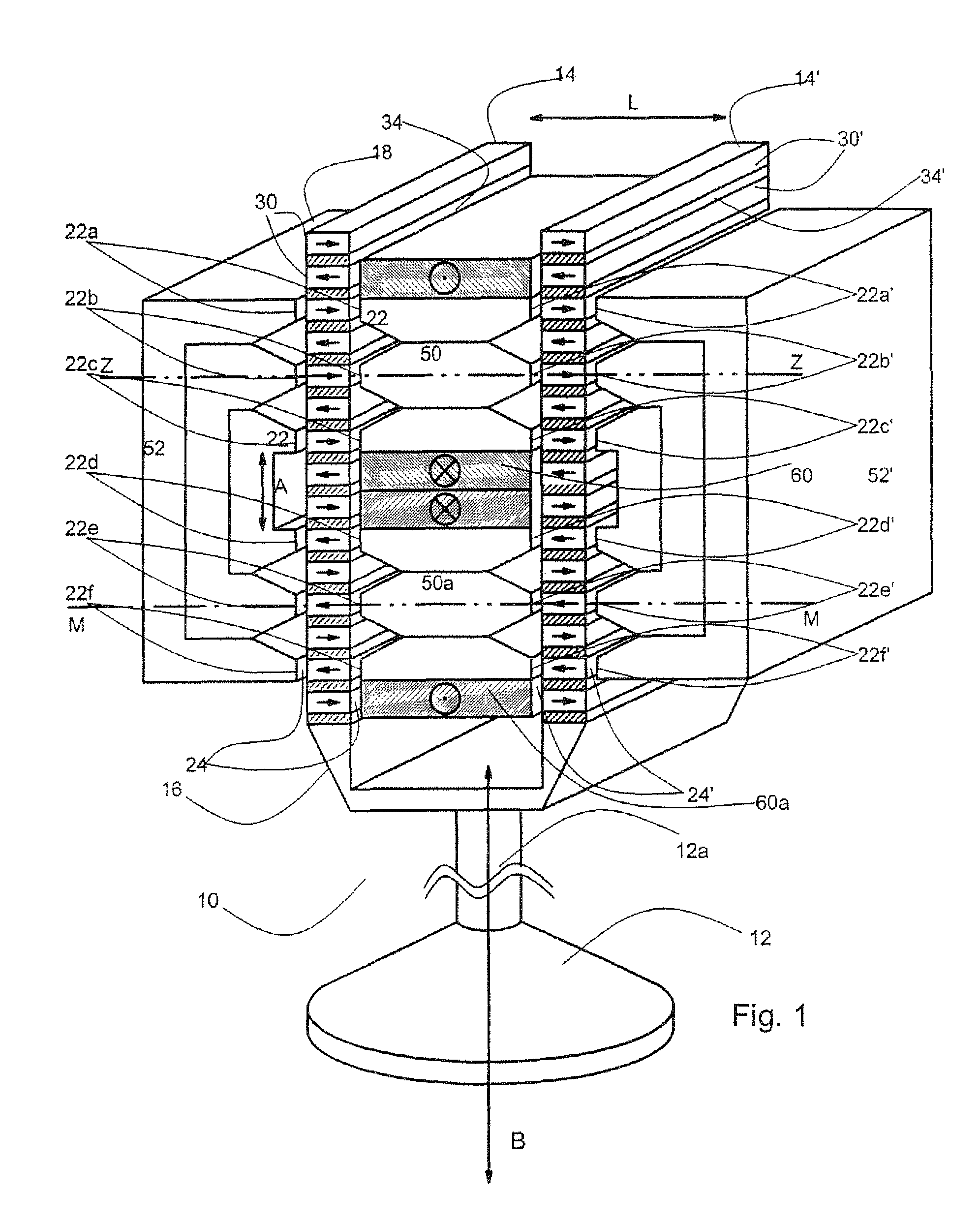
[0050]FIG. 1 illustrates a first form of embodiment of an electric linear motor 10 which serves, in the valve arrangement according to the invention, as an actuator for a valve member 12 belonging to a gas exchange valve, whose appertaining valve seat is not illustrated. The linear motor 10 has a rotor 16, which is coupled to the valve member 12 via a rod 12a, and a stator 18. Those skilled in the art understand that the term “rotor” is used broadly to identify a moving element even though the motion is translational and or rotational. In the following description the rotor 16 translates and reciprocates along its axis. Said rod 12a is provided with an apparatus, of which nothing further is illustrated but which permits rotation of the valve member 12 about its central longitudinal axis and makes it possible to compensate for dimensional tolerances.

[0051]The rotor 16 has two parallel stacks 14, 14′ which are arranged at a distance L from one another and consist of a large number of ...


PUM


Abstract

A gas exchange valve actuator for a valve-controlled internal combustion engine is equipped with a rotor, which is to be coupled to a valve member, and a stator, wherein the rotor has at least two stacks, which are arranged at a predetermined distance from one another, of superposed permanently magnetic bars, and the stator is formed, at least partially, from a soft-magnetic material and has at least two pairs of teeth with mutually opposed teeth, of which each pair of teeth receives one of the two stacks between them in each case, while forming an air gap, and wherein the stator has at least two magnetically conductive inner regions which are located between the two stacks and arranged at a predetermined distance from one another in the direction of movement of the rotor and which are at least partially surrounded, in each case, by an essentially hollow-cylindrical coil arrangement, the central longitudinal axis of which is oriented approximately transversely to the direction of movement of said rotor.

Description

CROSS-REFERENCE TO RELATED APPLICATIONS[0001]This is a continuation of International Patent Application No. PCT / EP2006 / 002967, filed Mar. 31, 2006.DESCRIPTION[0002]1. Background of the Invention[0003]The present invention relates to a gas exchange valve actuator for a valve-controlled internal combustion engine. In particular, the invention relates to a gas exchange valve in which the opening and closing movement of the valve member is not brought about and controlled by a camshaft. Instead, the valve member is actuated electrically in the case of the gas exchange valve according to the invention.[0004]2. Prior Art[0005]From JP-A-3-92518, a driving apparatus for a valve arrangement in internal combustion engines is known, in which the stator is composed of two approximately semi-cylindrical shells which have teeth which are divided, both in the peripheral direction and in the longitudinal direction of each shell, and which face towards the rotor. The individual teeth in each shell a...

Claims


Application Information

Patent Timeline
Patent Type & Authority Patents(United States)
IPC IPC(8): F01L9/04F01L9/20
CPCF01L9/04F01L2009/0405F01L2009/2105F01L9/20
Inventor GRUNDL, ANDREASHOFFMANN, BERNHARD
Owner COMPACT DYNAMICS
Why Eureka
Try Eureka