Linear Actuator in an Electric Percussion Tool

a technology of electric percussion and actuator, which is applied in the direction of portable percussive tools, electrical apparatus, dynamo-electric machines, etc., can solve the problems of low inert mass of the rotor and high stability

Inactive Publication Date: 2008-10-16
COMPACT DYNAMICS
View PDF26 Cites 15 Cited by
  • Summary
  • Abstract
  • Description
  • Claims
  • Application Information

AI Technical Summary

Problems solved by technology

As a result, the inert mass of the rotor is low, but its stability high.

Method used


Image

  • Linear Actuator in an Electric Percussion Tool
  • Linear Actuator in an Electric Percussion Tool
  • Linear Actuator in an Electric Percussion Tool

Examples


Embodiment Construction

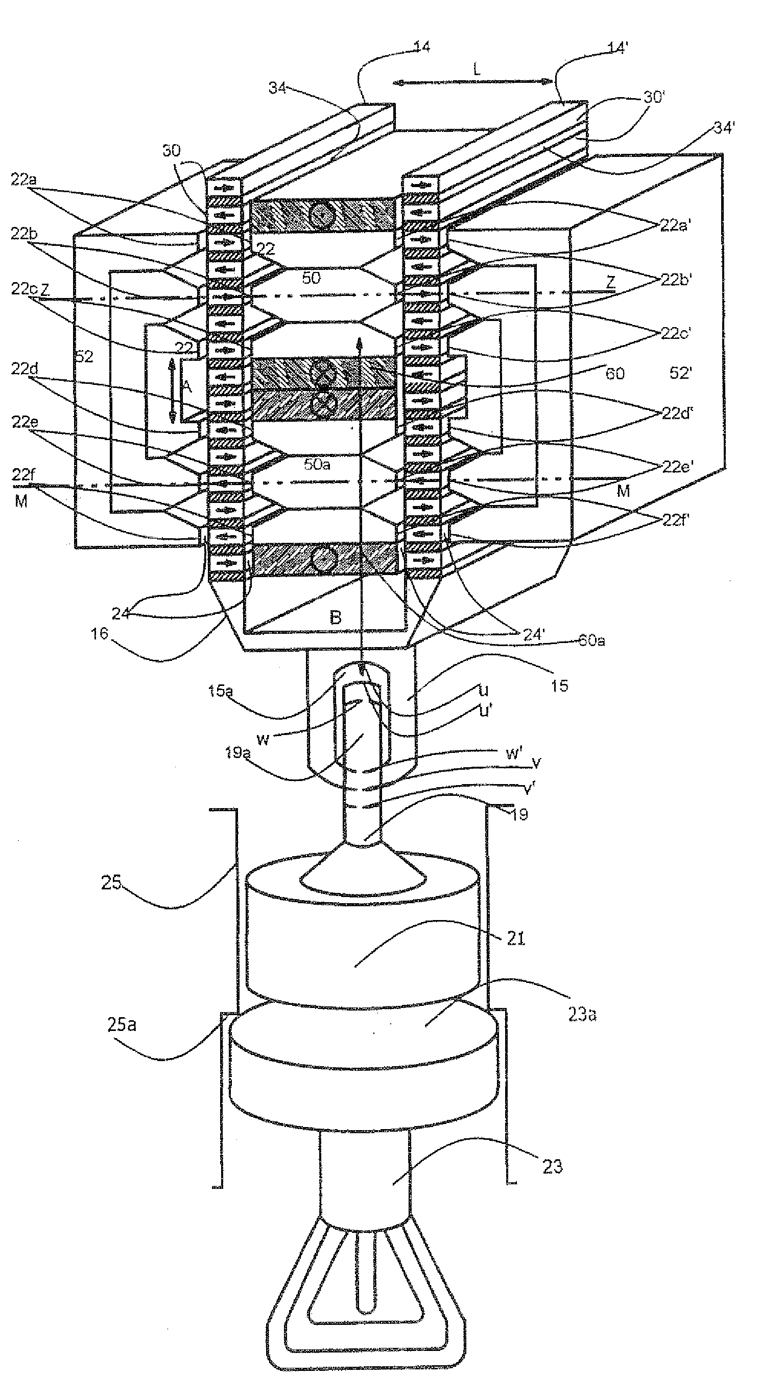
[0052]FIG. 1 illustrates a first form of embodiment of an electric linear actuator 10 in an electric percussion tool, which actuator has a rotor 16 and a stator 18. Those skilled in the art understand that the term “rotor” is used broadly to identify a moving element even though the motion is translational and or rotational. In the following description the rotor 16 translates and reciprocates along its axis.

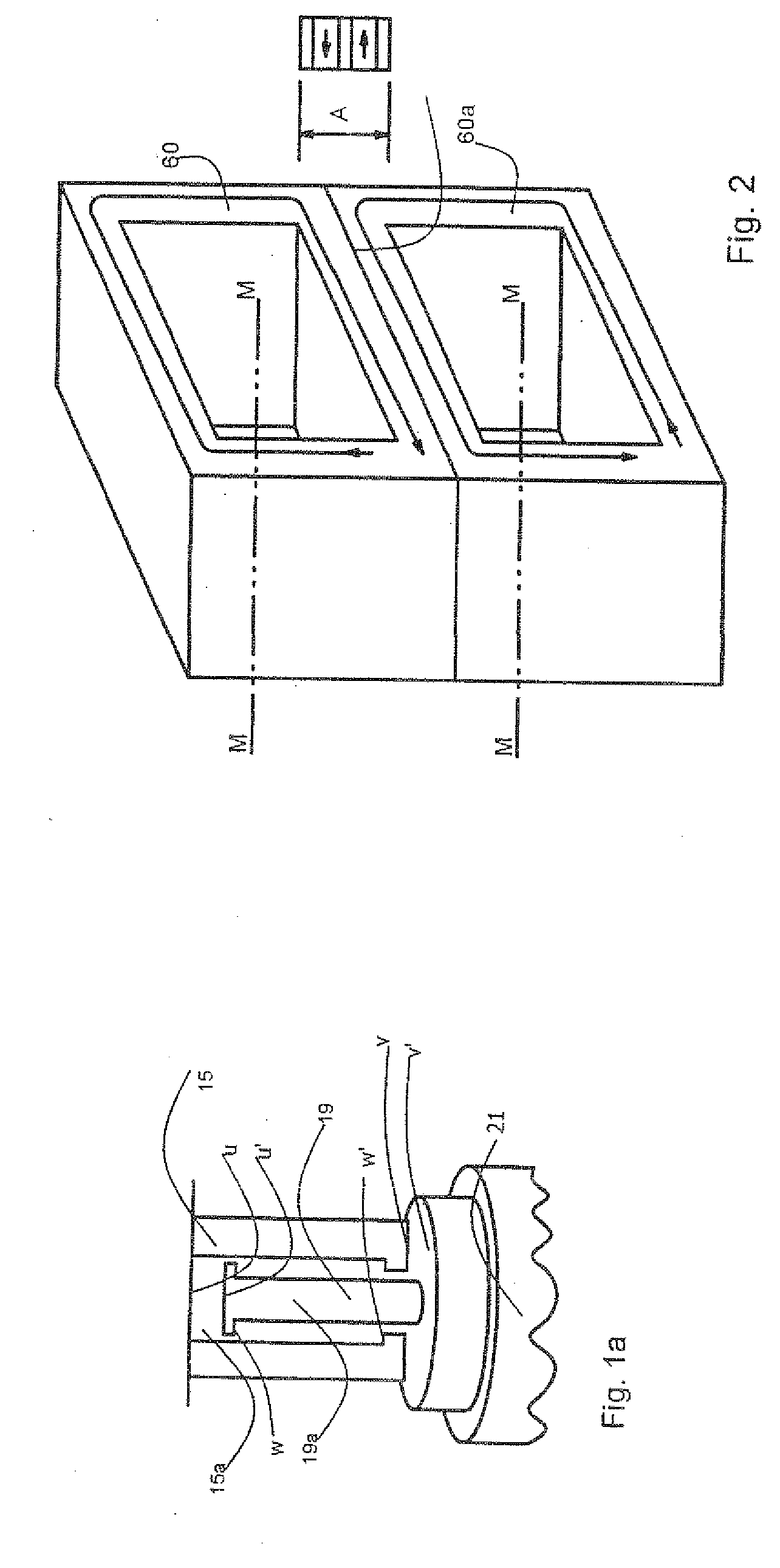
[0053]The rotor 16 has two parallel stacks 14, 14′ which are arranged at a distance L from one another and consist of a large number of superposed permanently magnetic bars 30, 30′ having an essentially parallelepipedal design.

[0054]The stator 18 is in the form of a soft-magnetic shaped body made of sintered ferrous metal powder or of stratified iron laminations. The stator 18 has a number of pairs of teeth 22a, 22a′; 22b, 22b′; 22c, 22c′; 22d, 22d′; 22e, 22e′; 22f, 22f′ having mutually opposed teeth 22. One of the two stacks 14, 14′ is received, in each case, between the teeth ...


PUM


Abstract

A linear actuator in an electric percussion tool is equipped with a rotor and a stator, wherein the rotor has at least two stacks, which are arranged at a predetermined distance from one another, of superposed permanently magnetic bars, the stator is formed, at least partially, from a soft-magnetic material and has at least two pairs of teeth with mutually opposed teeth, of which each pair of teeth receives one of the two stacks between them, in each case, while forming an air gap, and wherein the stator has at least two magnetically conductive inner regions which are located between the two stacks, are arranged at a predetermined distance from one another in the direction of movement of the rotor and are at least partially surrounded, in each case, by an essentially hollow-cylindrical coil arrangement, the central longitudinal axis of which is oriented approximately transversely to the direction of movement of the rotor, and the rotor has a driving element which is able to transmit a mechanical impulse to a tool belonging to the electric percussion tool.

Description

CROSS-REFERENCE TO RELATED APPLICATIONS[0001]This is a continuation of International Patent Application No. PCT / EP2006 / 002969, filed Mar. 31, 2006.BACKGROUND TO THE INVENTION[0002]The present invention relates to a linear actuator in an electric percussion tool, which actuator is to be operated electrically and has a rotor and a stator, wherein the rotor is set up to act upon a tool belonging to the electric percussion tool. Areas of application for electric percussion hammers of this kind are, for example, overground and underground construction, the construction of installations, concrete works, artificial stone factories, foundries, installation companies, the processing of natural and artificial stone and of every type of masonry and concrete, caulking, chiseling, breaking-up, excavating, granulating, beating, tamping and deburring, the breaking-up of concrete and asphalt and also rubble-permeated ground, the demolition of concrete, masonry and other building materials, the tear...

Claims


Application Information

Patent Timeline
Patent Type & Authority Applications(United States)
IPC IPC(8): H02K41/02
CPCB25D11/064H02K33/16
Inventor GRUNDL, ANDREASHOFFMANN, BERNHARD
Owner COMPACT DYNAMICS
Why Eureka
Try Eureka