Hydraulic energy accumulator

a technology of hydrostatic energy accumulator and accumulator, which is applied in the direction of electric generator control, machines/engines, mechanical equipment, etc., can solve the problems of kilowatt hour (kwh) sometimes being many times more expensive in peak demand time periods than in low demand periods

Inactive Publication Date: 2010-11-30
YSHAPE
View PDF28 Cites 53 Cited by
  • Summary
  • Abstract
  • Description
  • Claims
  • Application Information

AI Technical Summary

Problems solved by technology

For example, power consumption during a hot summer day may be considerably greater than for the night.
And typically the per unit cost of power is greater during a peak time period than for an off-peak or lower demand time period, with a kilowatt hour (KWH) sometimes being many times more expensive in peak demand time periods than in low demand periods.
Supply, delivery, and affordability of power during peak times can thus be problematic.
And yet some of the existing electricity re-distribution techniques have their own disadvantages and inefficiencies.

Method used


Image

  • Hydraulic energy accumulator
  • Hydraulic energy accumulator
  • Hydraulic energy accumulator

Examples


Embodiment Construction

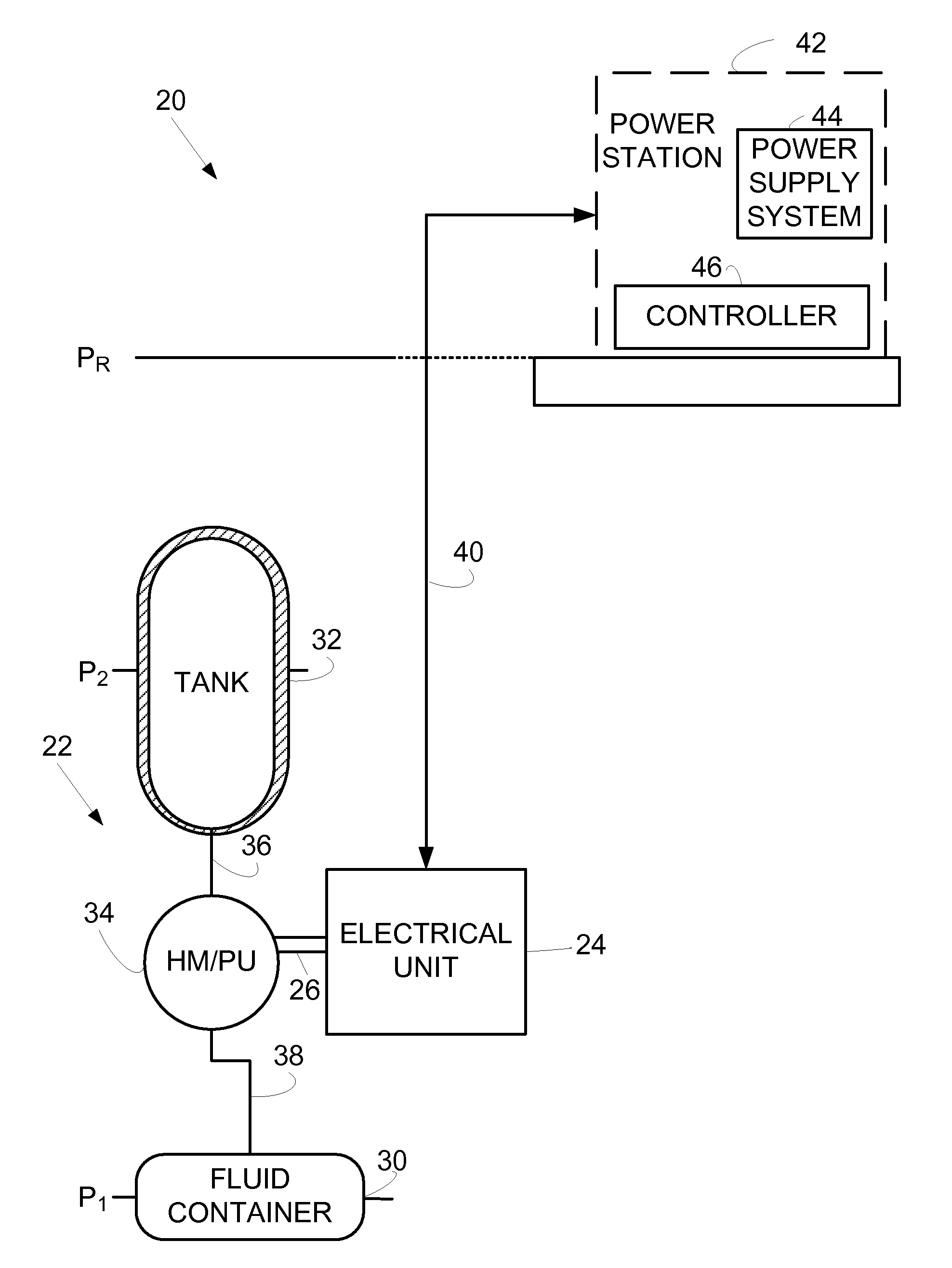
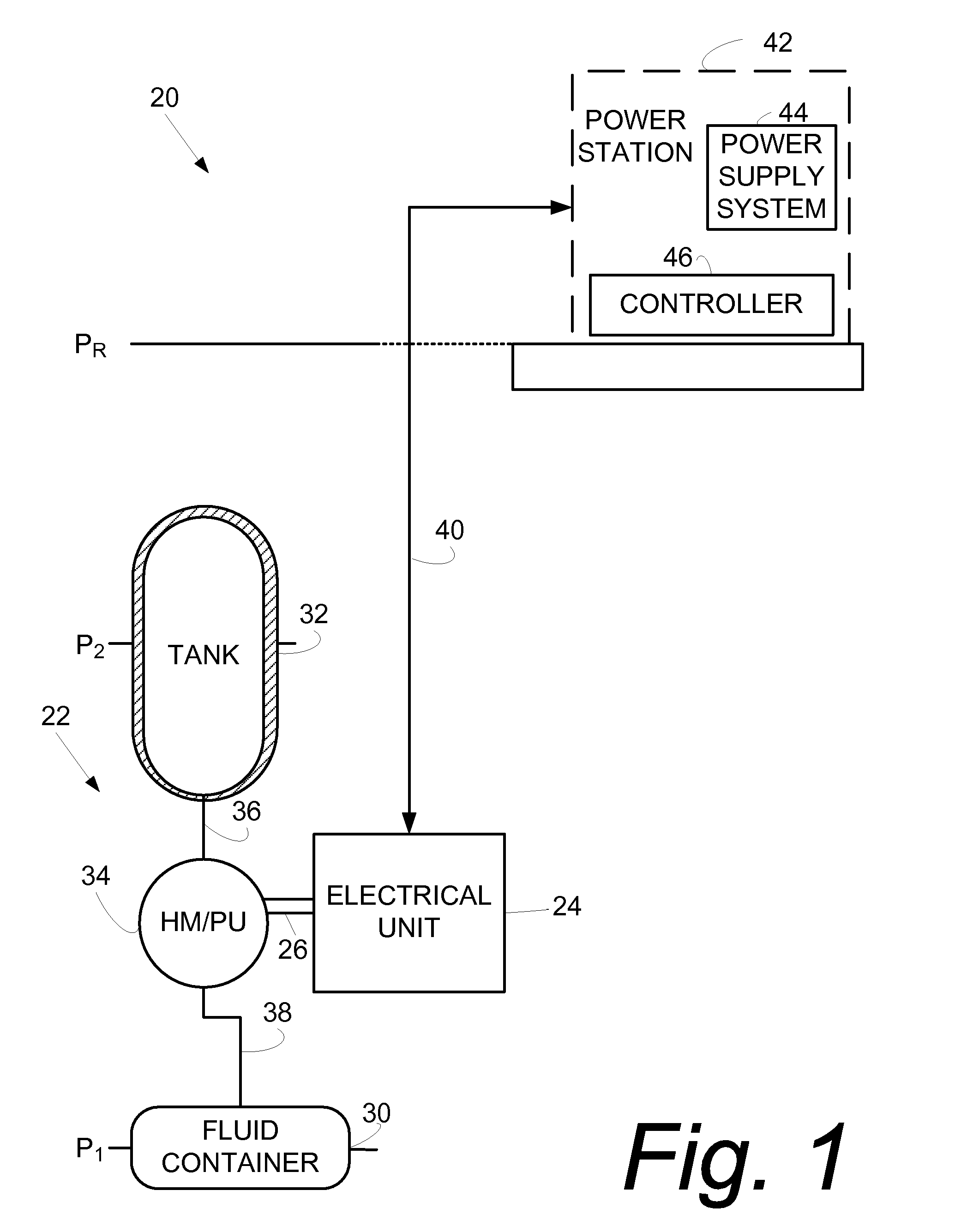
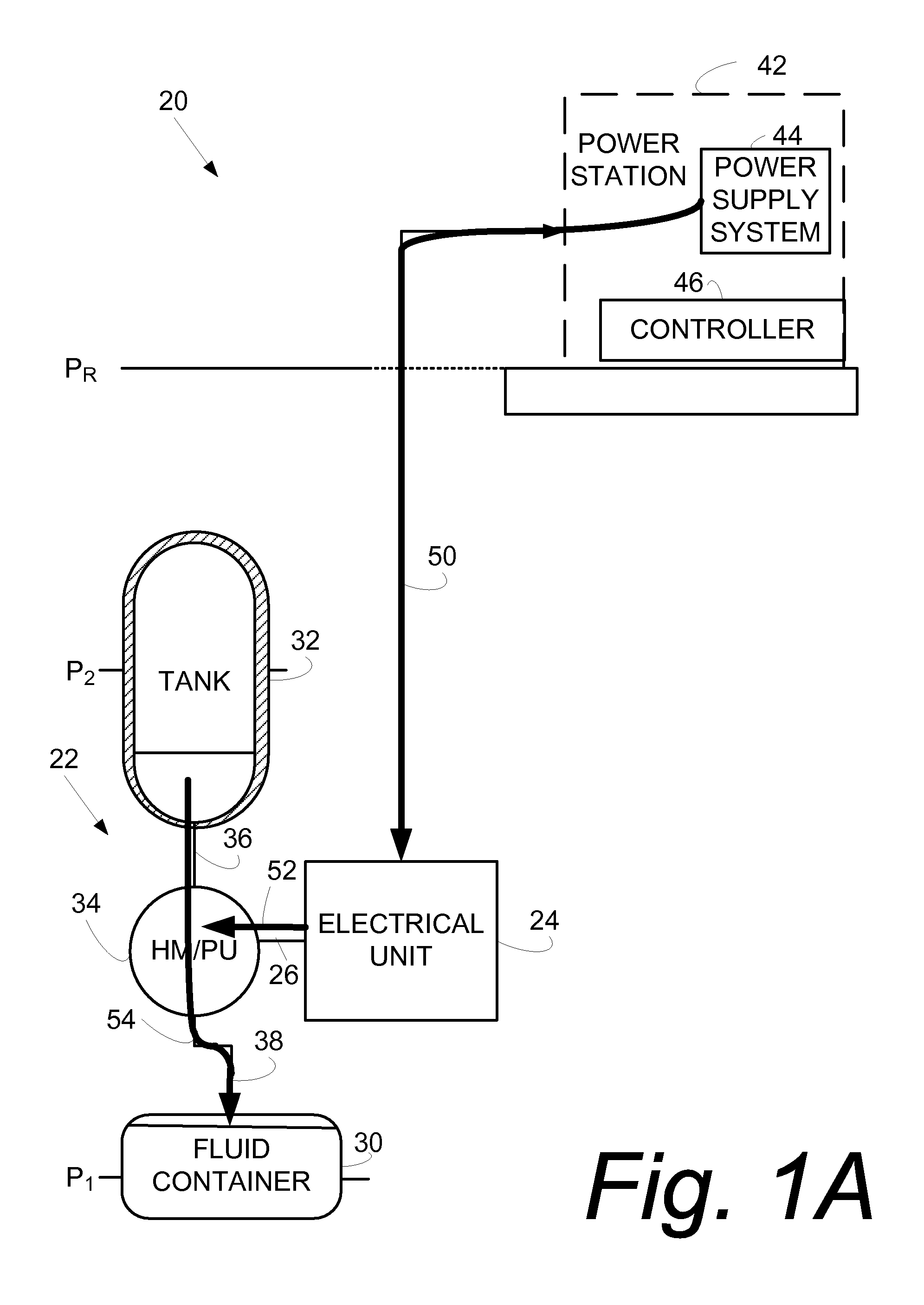
[0027]In the following description, for purposes of explanation and not limitation, specific details are set forth such as particular architectures, interfaces, techniques, etc. in order to provide a thorough understanding of the present invention. However, it will be apparent to those skilled in the art that the present invention may be practiced in other embodiments that depart from these specific details. That is, those skilled in the art will be able to devise various arrangements which, although not explicitly described or shown herein, embody the principles of the invention and are included within its spirit and scope. In some instances, detailed descriptions of well-known devices, circuits, and methods are omitted so as not to obscure the description of the present invention with unnecessary detail. All statements herein reciting principles, aspects, and embodiments of the invention, as well as specific examples thereof, are intended to encompass both structural and functiona...


PUM


Abstract

Example energy storage systems (20, 20′, 20″) comprises a fluid circuit (22, 22′, 22″) and an electrical unit (24, 24′, 24″) configured to operate as a motor in a first phase of operation and to operate as a generator in a second phase of operation. The fluid circuit (22, 22′, 22″) comprises a first fluid container (30, 30′, 30″) situated so content of the first fluid container experiences a first pressure level; a tank (32, 32′, 32″) having its content at a second pressure level (the second pressure level being less than the first pressure level): and, a first hydraulic motor / pump unit (34, 134, 34″connected to communicate a first working fluid between the tank and the first fluid container. In the first phase of operation electricity is supplied to the first hydraulic / motor unit (34, 134, 34″) whereby the first hydraulic / motor unit transmits the first working fluid from the tank into the first fluid container (30, 30′, 30″). In the second phase of operation pressurized first working fluid in the first fluid container (30, 30′, 30″) is transmitted from the first fluid container through the first hydraulic / motor unit 34, 134, 34″) to the tank (32, 32′, 32″), thereby causing the electrical unit (24, 24′, 24″) to generate electricity.

Description

[0001]This application claims the priority and benefit of U.S. Provisional Patent Application 60 / 867,658, filed Nov. 29, 2006, entitled “Hydraulic Energy Accumulator”, which is incorporated herein by reference in its entirety.BACKGROUND[0002]I. Technical Field[0003]This invention pertains to the storage of energy, and particularly to the storage of electricity during a low demand time period for retrieval during a high demand time period.[0004]II. Related Art and Other Considerations[0005]In many geographical or utility service areas the demand for electricity varies during a day or other time period. For example, power consumption during a hot summer day may be considerably greater than for the night. And typically the per unit cost of power is greater during a peak time period than for an off-peak or lower demand time period, with a kilowatt hour (KWH) sometimes being many times more expensive in peak demand time periods than in low demand periods.[0006]Supply, delivery, and affor...

Claims


Application Information

Patent Timeline
Patent Type & Authority Patents(United States)
IPC IPC(8): F03B13/10F03B13/12H02P9/04F02B63/04
CPCF15B1/024
Inventor GOGOANA, MARIAN V.WHITTTAKER, JAMES B.
Owner YSHAPE
Why Eureka
Try Eureka