Dielectric resonator filter having a tunable element eccentrically located and a method of production thereof

a dielectric resonator and eccentric arrangement technology, applied in the field of radiofrequency engineering, can solve the problems of difficult to achieve the comparatively high accuracy and reproducibility of the disk position, the adjustment mechanism that is required for the linear movement requires a large amount of space, and the feasibility is more than questionable, etc., to achieve cost-effective production, good radio frequency characteristics, and compact and robust design

Active Publication Date: 2010-11-30
THALES SUISSE
View PDF11 Cites 2 Cited by
  • Summary
  • Abstract
  • Description
  • Claims
  • Application Information

AI Technical Summary

Benefits of technology

[0012]One object of the invention is thus to provide a tunable radio-frequency filter arrangement which can be produced cost-effectively, is distinguished by a particularly compact and robust design with good radio-frequency characteristics, and has an advantageous tuning response, and to specify a cost-effective and simple method for its production.
[0013]The essence of the invention is to provide, as a tunable filter module, a cavity with a dielectric resonator element which is arranged in a fixed position and has an eccentric cutout in which a dielectric body is arranged such that it can rotate. The arrangement of the body such that it can rotate in the cutout allows the dielectric resonator element to be designed to be extremely compact. The rotary movement can be designed with high precision, thus allowing high tuning accuracy and reproducibility to be achieved.
[0023]Particularly reliable tuning with high reproducibility is achieved in that, a controller, which has a control block, a memory and an input unit, is provided in the eccentric cutouts in the dielectric resonator bodies in order to control the rotation of the dielectric bodies, in that position sensors, in particular in the form of light barriers which are connected to the control block, are provided in order to determine the initial position of the dielectric bodies in the radio-frequency filter arrangement, and in that value tables are stored in the memory and associate an appropriate angle position of the dielectric bodies with a small number of selected frequencies of the radio-frequency filter arrangement.
[0024]One preferred refinement of the method according to the invention is distinguished in that the sheet-metal parts are silver-plated, and are soldered to one another by means of a silver solder, the sheet-metal parts have mounting aids, in particular in the form of crossing slots, mounting slots and mounting lugs which are matched to one another, in that the sheet-metal parts are initially loosely plugged together by means of the mounting aids and the crossing slots, mounting slots and mounting lugs in order to form the filter housing, and the plugged-together filter housing is made mechanically robust by pushing the mounting lugs into the mounting slots, in that silver solder, preferably in paste form, is applied to the junction points between the plugged-together sheet-metal parts, and in that the plugged-together sheet-metal parts are heated, preferably in an oven, until the silver solder melts and flows into the junction points.
[0025]The production process is particularly simple and cost-effective if all of the sheet-metal parts of a filter housing are cut from a common metal sheet, which has not been silver-plated, by means of a cutting method, preferably by means of laser cutting, in such a way that the cut-out sheet-metal parts are connected to the remaining area of the metal sheet only by a small number of narrow webs, in that the metal sheet together with the cut-out sheet-metal parts is then silver-plated, in that the sheet-metal parts are detached from the metal sheet after being silver-plated, and are then used to construct the filter housing, in particular with the majority of the webs remaining at those points on the sheet-metal parts which are located outside the cavities when the filter housing is complete.

Problems solved by technology

This known filter arrangement has various disadvantages: firstly, it is comparatively difficult to achieve the comparatively high accuracy and reproducibility of the disk position during a linear movement of the moveable disk, as is required for good tunability of the filter.
Secondly, the adjustment mechanism that is required for the linear movement requires a very large amount of space.
Furthermore, no mechanically adjustment mechanism is specified either, so that this proposal should in fact be regarded just as paper prior art, and its feasibility is more than questionable.
In particular, this solution proposal is also subject to the same disadvantages resulting from the linear movement as those which have already been discussed further above.

Method used


Image

  • Dielectric resonator filter having a tunable element eccentrically located and a method of production thereof
  • Dielectric resonator filter having a tunable element eccentrically located and a method of production thereof
  • Dielectric resonator filter having a tunable element eccentrically located and a method of production thereof

Examples


Embodiment Construction

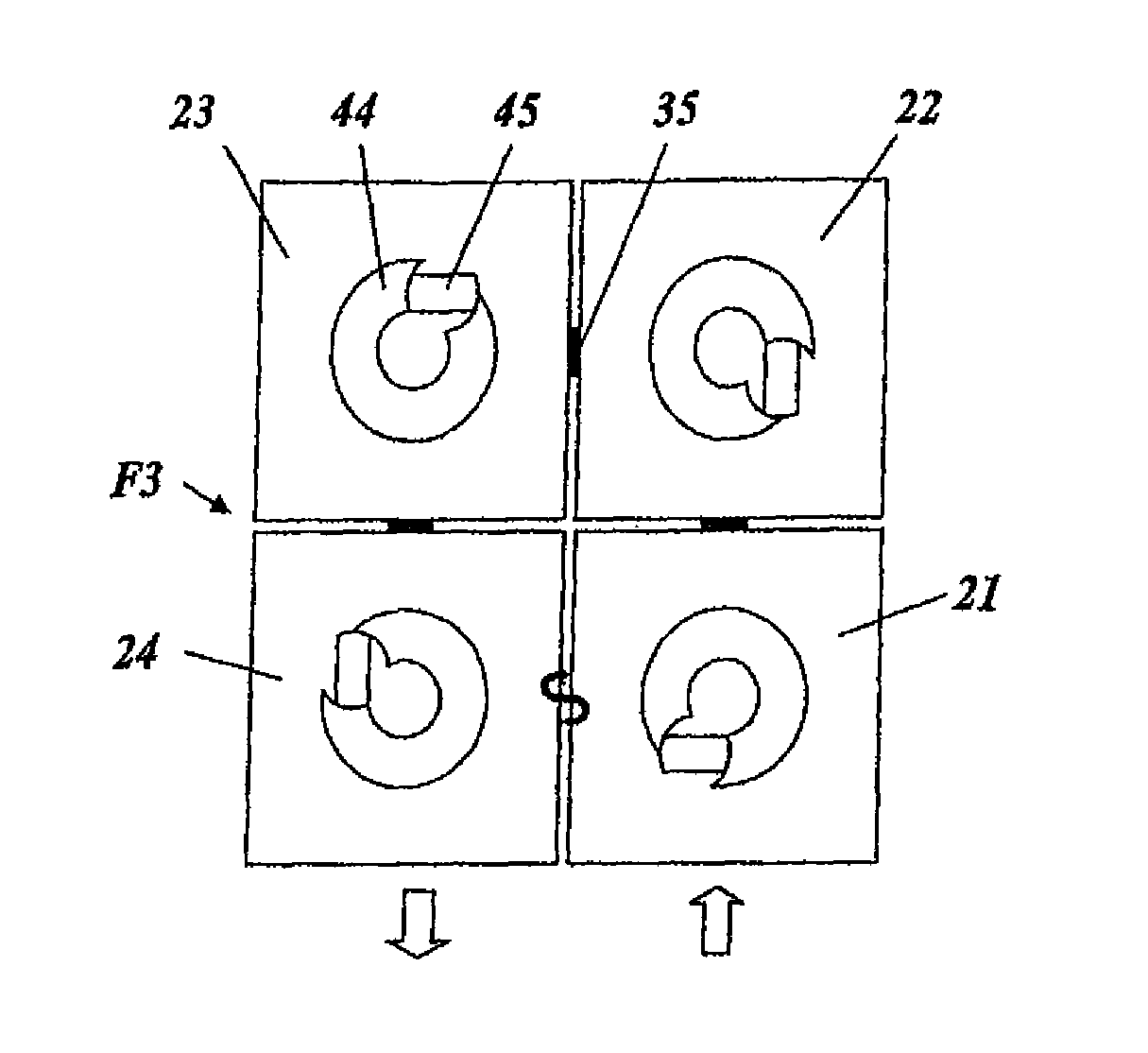
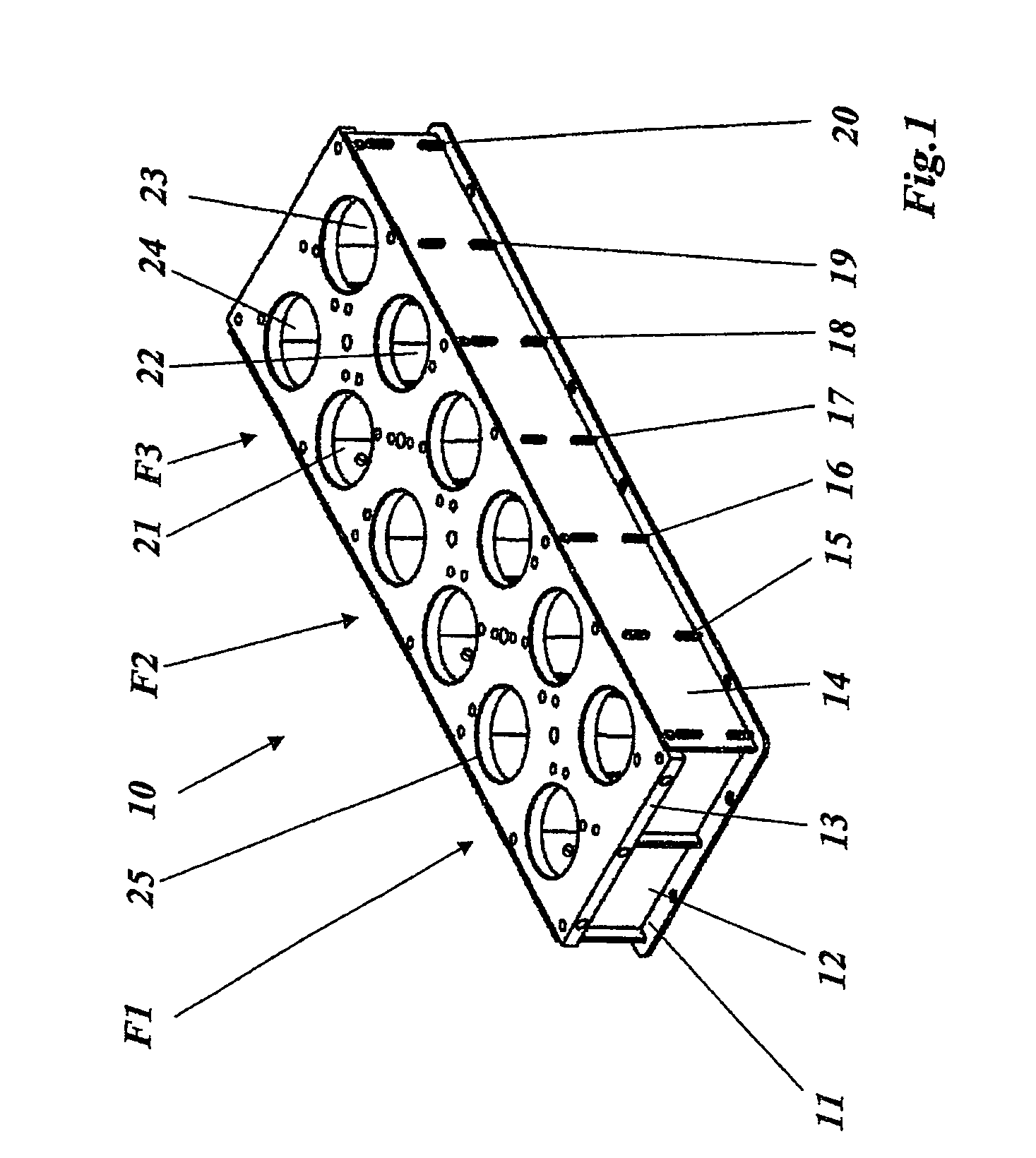
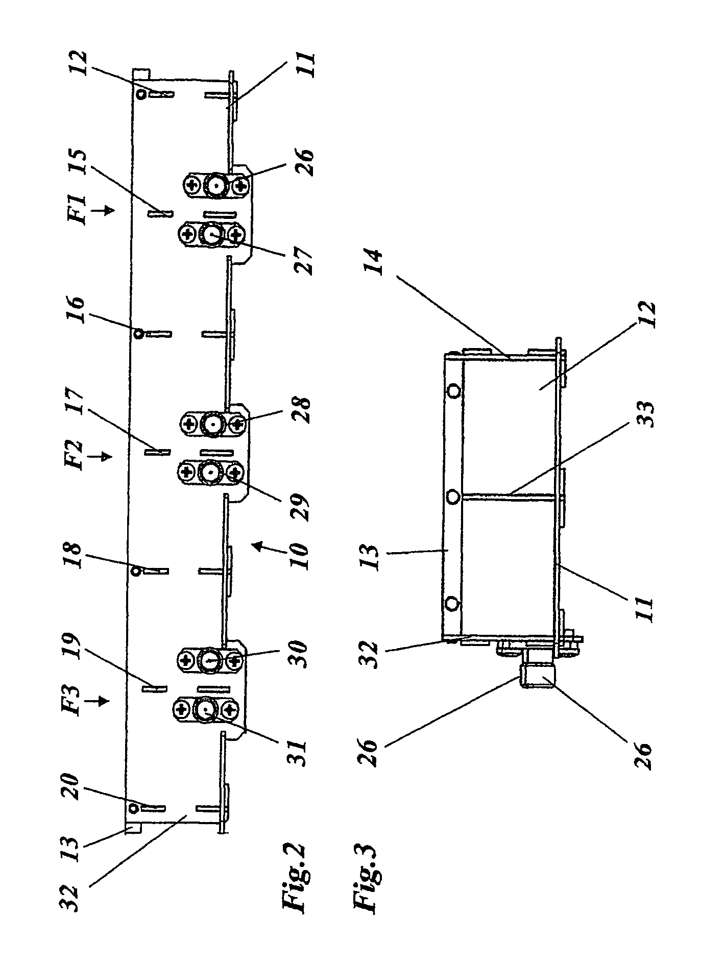
[0047]The tunable radio-frequency filter arrangement which is described in the following text has a filter housing (10FIG. 1) in which a number of tuning units (40 in FIG. 8) are inserted and are screwed to the motor mounting plate (13 in FIG. 1). The filter housing and the tuning units will be explained separately. The completely assembled filter arrangement is not illustrated, for reasons of clarity.

[0048]The rectangular filter housing (filter box) 10 illustrated in FIG. 1 is composed of a thicker (at the top) motor mounting plate 13 and of a number of sheet-metal parts, which form the base, side walls and (inner) separating walls of the filter housing 10. The sheet-metal parts include the baseplate 11, which is illustrated individually in FIG. 7, the wall plates 12 and 20 (see also FIG. 4) which run in the transverse direction, the wall plates 14 and 32 (FIGS. 1, 2 respectively) which run in the longitudinal direction, the transverse (inner) separating plates 15, 17,19 which are ...


PUM


Abstract

A high-frequency filter arrangement comprising at least one filter consisting of a plurality of high-frequency inter-coupled cavities in which a locally fixed respective dielectric resonator element is disposed and in which a respective dielectric body can be modified, in order to tune the frequency of the filter, in the position thereof in relation to the dielectric resonator element. The structure of the inventive filter arrangement is simple, compact and economical and excellent filter and tuning properties are obtained by virtue of the fact that the dielectric body is arranged in an eccentric recess of the dielectric resonator element and that the dielectric body is rotatably arranged in the eccentric recess.

Description

CROSS-REFERENCE TO RELATED APPLICATIONS[0001]The present Application is based on International Application No. PCT / CH2003 / 000748, filed on Nov. 14, 2003, which in turn corresponds to FR 2112 / 02 filed on Dec. 11, 2002, and priority is hereby claimed under 35 USC §119 based on these applications. Each of these applications are hereby incorporated by reference in their entirety into the present application.BACKGROUND OF THE INVENTION[0002]1. Field of the Invention[0003]The invention relates to the field of radio-frequency engineering. It relates in particular to a tunable radio-frequency filter arrangement and to a method for its production.[0004]A radio-frequency filter arrangement of this type is known, for example, from U.S. Pat. No. 6,147,577.[0005]A single tunable dielectric resonator, in which the moving dielectric body can move linearly in the vertical or horizontal direction in a cutout in the dielectric resonator element is known, by way of example, from EP-A1-0 601 369.[0006]...

Claims


Application Information

Patent Timeline
Patent Type & Authority Patents(United States)
IPC IPC(8): H01P1/20H01P1/208H01P7/10
CPCH01P1/2084H01P7/10H01P1/20
Inventor KLEY, THOMASRHOMBERG, BRUNOHEINZE, DANIEL
Owner THALES SUISSE
Why Eureka
Try Eureka