Microscopic inspection apparatus for reducing image smear using a pulsed light source and a linear-periodic superpositioned scanning scheme to provide extended pulse duration, and methods useful therefor

a scanning scheme and microscopic inspection technology, applied in the field of scanning schemes, can solve the problems of limited power, short pulses with high instantaneous power, and limited power of pulsed sources for scanning imaging schemes

Inactive Publication Date: 2010-11-30
APPL MATERIALS ISRAEL LTD
View PDF7 Cites 2 Cited by
  • Summary
  • Abstract
  • Description
  • Claims
  • Application Information

AI Technical Summary

Benefits of technology

[0004]The present invention seeks to provide improved methods and systems for automatic optical inspection of objects with microscopic features, such as but not limited to wafers, flat panel displays, and integrated circuits. According to certain embodiments of the present invention, a linear scan with a slight sine modulation is used, thereby to create time intervals in which a stage holding an object to be inspected, is virtually at rest. This enables use of light pulses, e.g., pulses of LED (light-emitting diode) illumination, having a relative long duration hence a desirably high per-pulse energy content. Since the light energy of light emitting diodes (LEDs) is substantially proportional to their pulse duration, a higher signal-to-noise ratio (SNR) and in addition or alternatively, a higher average scanning speed may thereby be achieved, without smearing the resulting image.
[0007]The present invention seeks to provide a scanning scheme which effectively uses LEDs as a cost-effective alternative for a pulsed light source for the strobing scheme. According to a preferred embodiment of the present invention, the linear scanning scheme which is provided in conventional microscopic inspection systems is replaced by a scheme which provides an object velocity, relative to the scanning components whose velocity is a superposition of the conventional linear velocity and a harmonic velocity such as a sine-shaped velocity. While this scanning scheme may be designed to maintain the average scanning speed, it provides for periods with very small speed, which enables to use the LEDs with longer pulse durations, up to 2 orders of magnitude, during those periods, without increasing the image smear.
[0010]Further provided, in accordance with an embodiment of the present invention, is a method for inspecting an article, comprising bringing at least a portion of the article into fields of view of at least one of a plurality of objective modules, adjusting an image selection mirror mechanism to sequentially direct images of the field of view from the objective modules to at least one camera which is shared by the objective modules and which has a field of view, capturing the images with the shared camera, processing the captured images to detect defects in the article; and lessening motion of at least one image of the article within the field of view of at least one camera, during image capture by the camera.

Problems solved by technology

However, their use as a pulsed source for strobing imaging schemes is limited because, unlike lasers or flash lamps, they cannot generate short pulses with high enough instantaneous power.
In fact, their power is limited by the instantaneous current, and the latter cannot be increased significantly, even for short pulses, without damaging the LED.

Method used


Image

  • Microscopic inspection apparatus for reducing image smear using a pulsed light source and a linear-periodic superpositioned scanning scheme to provide extended pulse duration, and methods useful therefor
  • Microscopic inspection apparatus for reducing image smear using a pulsed light source and a linear-periodic superpositioned scanning scheme to provide extended pulse duration, and methods useful therefor
  • Microscopic inspection apparatus for reducing image smear using a pulsed light source and a linear-periodic superpositioned scanning scheme to provide extended pulse duration, and methods useful therefor

Examples


Embodiment Construction

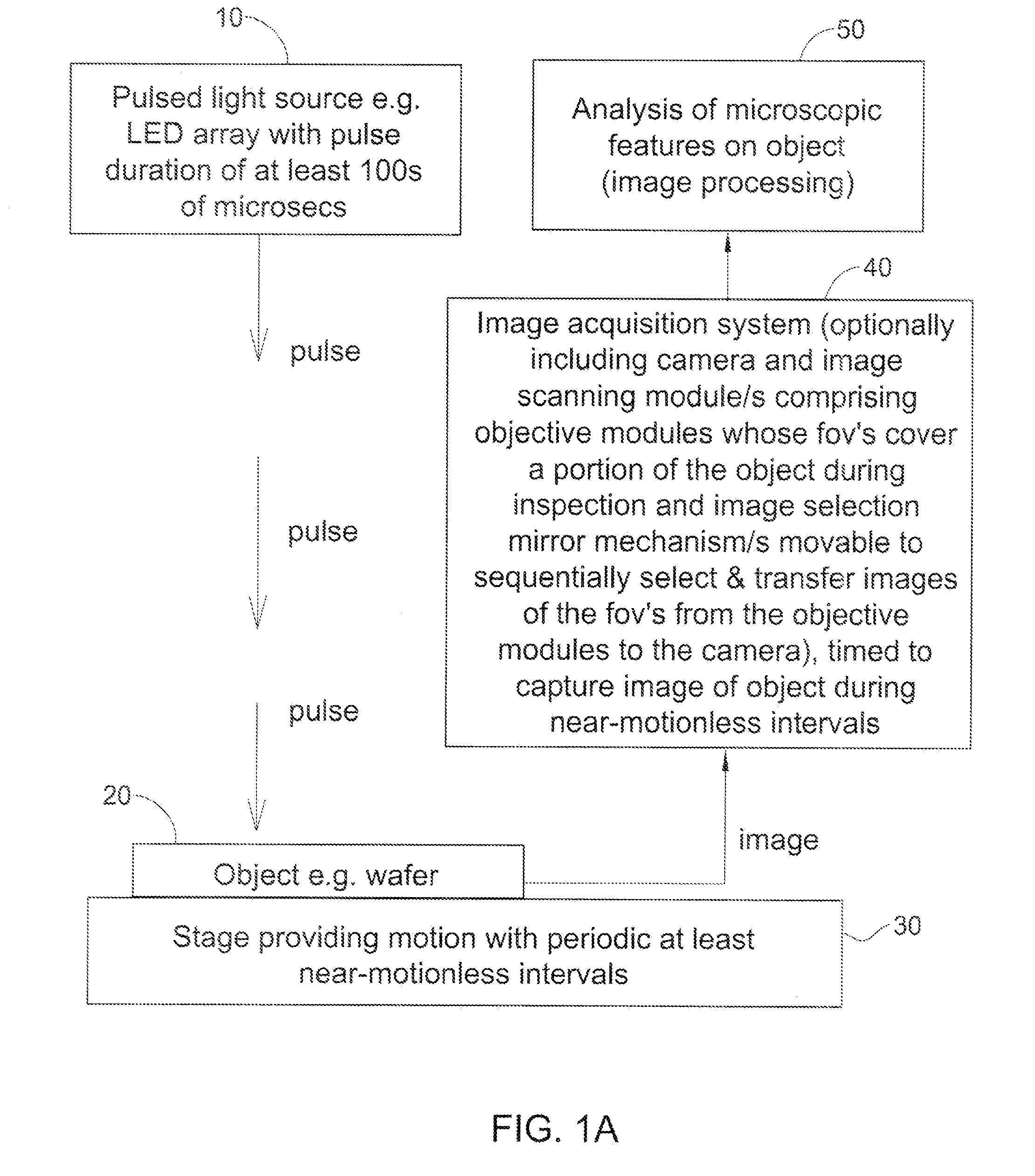
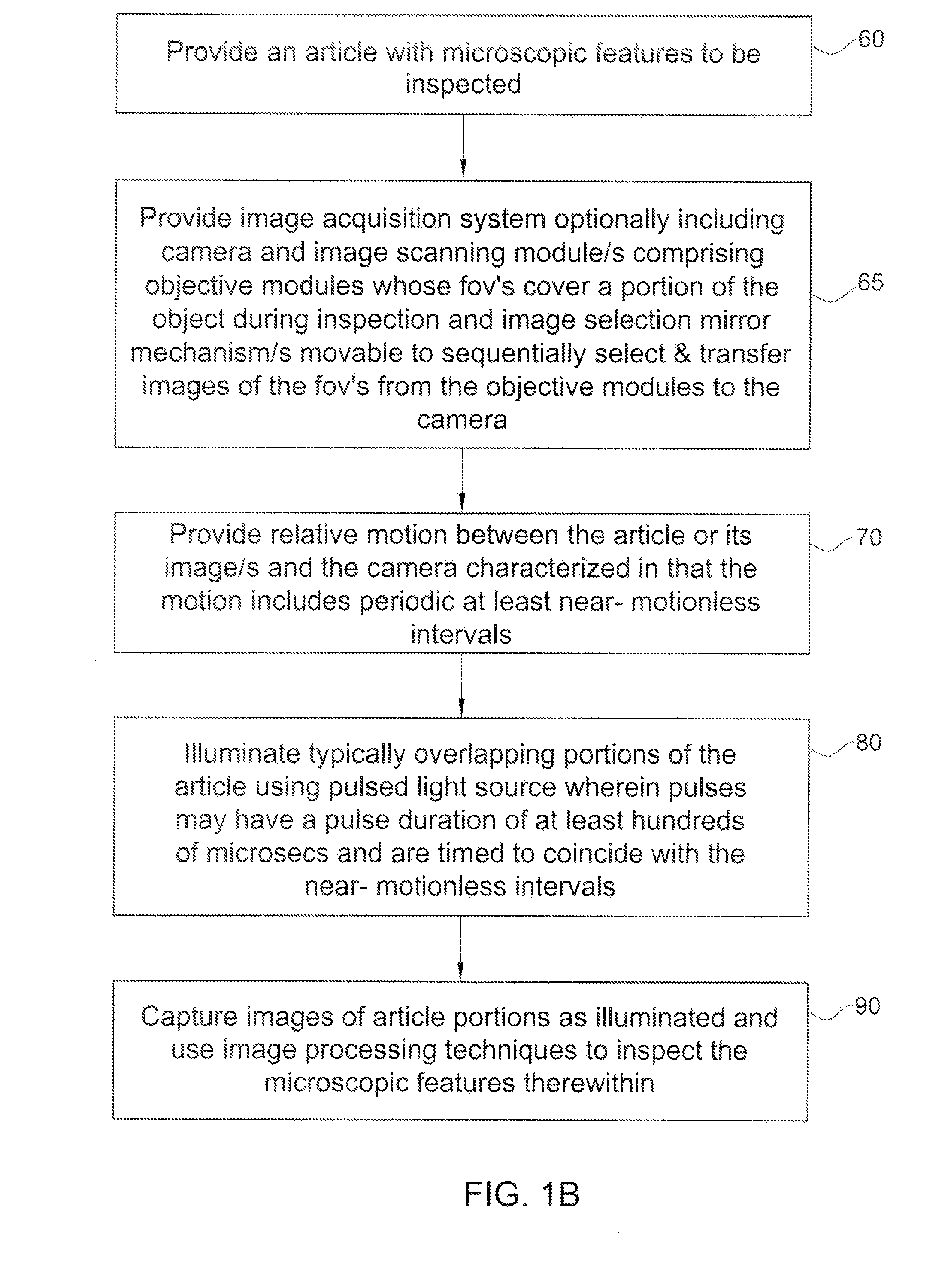
[0021]Reference is now made to FIG. 1A which is a simplified functional block diagram of a system for automatic optical inspection of objects constructed and operative in accordance with a preferred embodiment of the present invention. As shown, a pulsed LED array providing illumination whose pulse duration is, preferably, at least hundreds of microseconds, illuminates an object 20 with microscopic features to be inspected. The object 20 typically rests on a conventional x-y stage characterized in that the stage moves the object vis-à-vis the image acquisition system 40, or vice versa, such that the resulting relative motion is characterized by repeated, preferably periodic, at least near-motionless intervals. The operation of the image acquisition system 40 is timed such that images of the object are captured during these near-motionless intervals. The output of the image acquisition system 40 is analyzed by a conventional image processing unit so as to provide inspection data pert...


PUM


Abstract

An automated optical inspection system includes a pulsed light source illuminating an article to be inspected thereby to generate at least one image thereof, at least one camera having a field of view, and a relative motion provider operative to provide relative motion between the camera and at least one image of at least a portion of the article. The relative motion provider may include a first continuous motion provider and a second, velocity-during-imaging-lessening motion provider. The relative motion is a superposition of a first continuous component of motion provided by the first motion provider and a second, smaller component of motion provided by the second motion provider which lessens the velocity of the at least one image relative to the camera, during imaging.

Description

RELATED APPLICATIONS[0001]The present application is a non-provisional of and claims priority to co-pending U.S. Provisional Application No. 60 / 725,902, filed 12 Oct. 2005, entitled “Reducing image smear with LEDs using linear-sine scan (LISI) with extended pulse duration”, incorporated herein by reference.FIELD OF THE INVENTION[0002]The present invention relates generally to automatic optical inspection of objects with microscopic features and specifically to scanning schemes useful in conjunction therewith.BACKGROUND[0003]A wide variety of automatic optical inspection systems, such as those marketed by Applied Materials, Orbotech, KLA and Negevtech, are known.SUMMARY OF THE INVENTION[0004]The present invention seeks to provide improved methods and systems for automatic optical inspection of objects with microscopic features, such as but not limited to wafers, flat panel displays, and integrated circuits. According to certain embodiments of the present invention, a linear scan with...

Claims


Application Information

Patent Timeline
Patent Type & Authority Patents(United States)
IPC IPC(8): G06K9/00
CPCG06T7/0004G06T2207/10016G06T2207/10056G06T2207/10152G06T2207/30148
Inventor TIROSH, EHUD
Owner APPL MATERIALS ISRAEL LTD
Why Eureka
Try Eureka