Dynamic motion compensation for orientation instrumentation
What is AI technical title?
AI technical title is built by PatSnap AI team. It summarizes the technical point description of the patent document.
a technology of dynamic motion compensation and orientation instruments, applied in the direction of speed measurement using gyroscopic effects, instruments, complex mathematical operations, etc., can solve the problem of large orientation errors, and achieve the effect of accurate orientation readings
Inactive Publication Date: 2010-11-30
P&I
View PDF13 Cites 77 Cited by
Summary
Abstract
Description
Claims
Application Information
AI Technical Summary
This helps you quickly interpret patents by identifying the three key elements:
Problems solved by technology
Method used
Benefits of technology
Benefits of technology
[0012]In a tilt-compensated compass, the instant invention provides a solution to motion induced orientation errors by correcting a tilt reading during periods of movement and calculating a tilt compensated heading reading, thus giving accurate orientation readings. Using a local magnetic field provides an independent rotation reference without the expense and limitations of one primary alternative, gyroscope integration.
Problems solved by technology
Most tilt sensors are sensitive to motion acceleration distinct from the acceleration of gravity, which can result in large orientation errors during periods of movement.
Method used
Image
Click on the blue label to locate the original text in one second.
Reading with bidirectional positioning of images and text.
Examples
Embodiment Construction
Motion Compensation
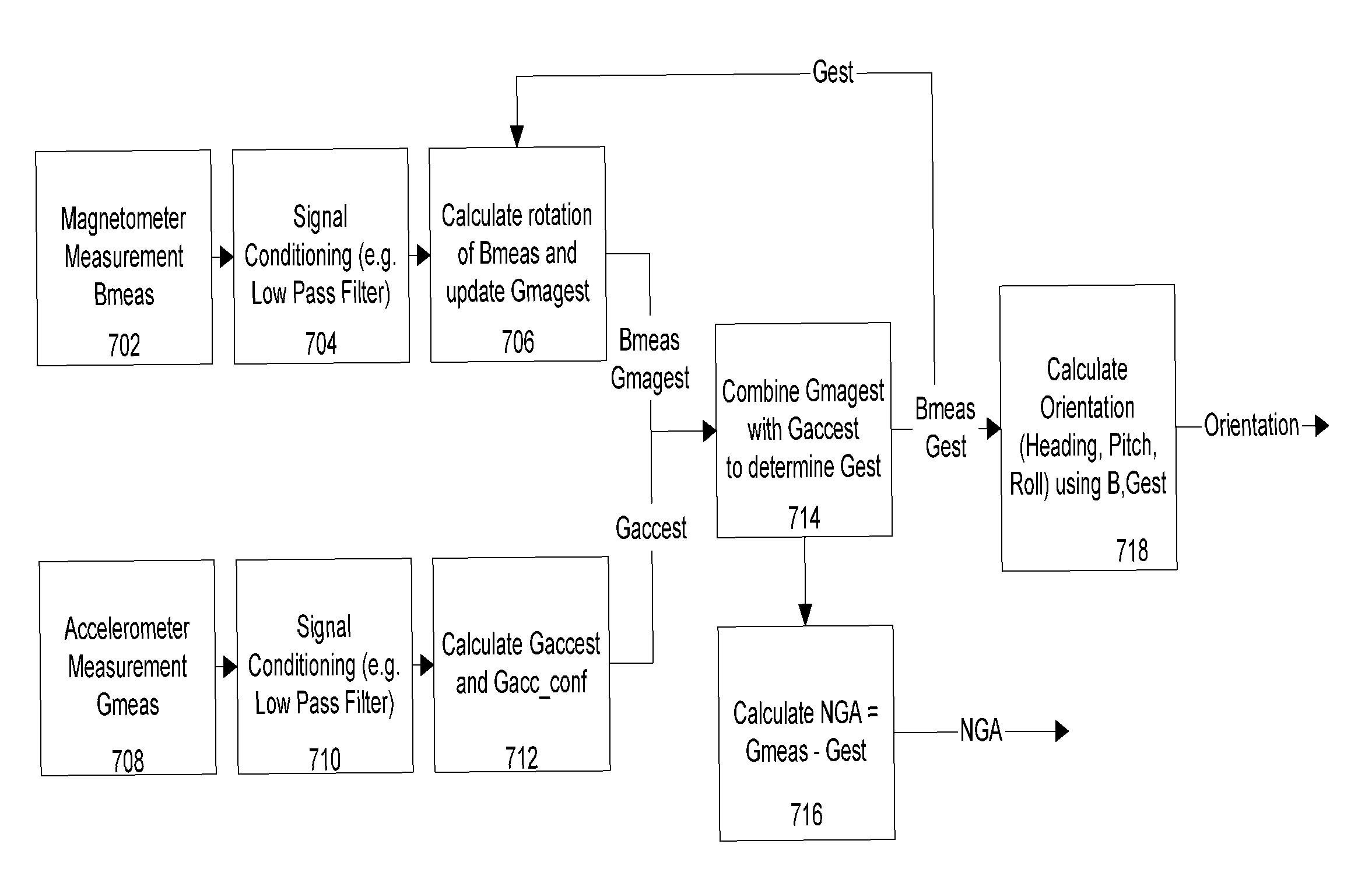
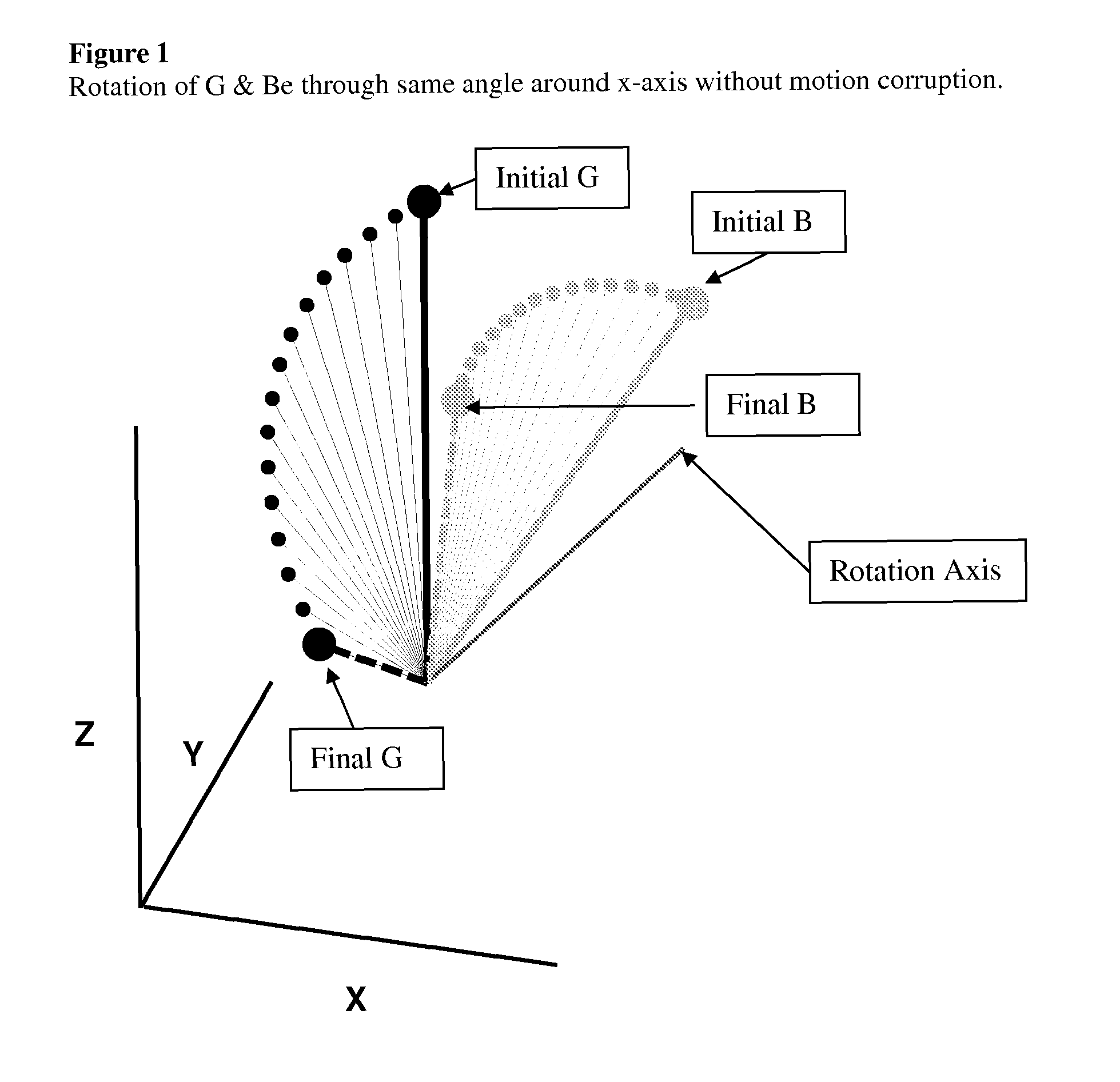
[0054]In one embodiment, a tilt compensated compass comprises at least two and optionally, three magnetic sensors (x, y, z) and at least one and optionally, two or three accelerometer sensors (x, y, z). When the compass is not being accelerated, accelerometers provide an accurate reference of horizontal for determining a north component of the earth's local magnetic field. Upon moving a tilt compensated compass, accelerometer readings include a motion induced component in addition to an earth gravity component, resulting in orientation error. However, if a tilt compensated compass traces the path of a three dimensional, 3D, earth magnetic field vector (B), a tilt compensated compass can sense and track the direction and magnitude of the rotation which has occurred since the last measurement. Sensing a rotation recorded by B, a tilt compensated compass can use this to isolate the non-gravity accelerations (NGA) and the gravitational vector (G) from one or more acce...
PUM
Abstract
The instant invention discloses a method for an orientation measuring instrument to isolate and separate gravitational and non-gravitational components of acceleration from accelerometer measurements by using an ambient magnetic field, typically the earth's magnetic field, as a fixed rotation reference. Using magnetic field measurements, one can track changes in orientation of a device and use that information to determine the gravitation direction, during periods when acceleration measurements include non-gravitational acceleration combined with gravitational acceleration components. In addition to determining orientation, a method and associated instrument provide a non-gravity acceleration vector of the device.
Description
PRIORITY[0001]Applicant claims priority from U.S. Provisional application Ser. No. 60 / 956,907 filed on Aug. 20, 2007.CROSS-REFERENCE TO RELATED APPLICATIONS[0002]The prior art for the present invention is found in U.S. Pat. No. 4,851,775, U.S. Pat. No. 5,239,264, U.S. Pat. No. 5,381,603, U.S. Pat. No. 6,243,660, U.S. Pat. No. 6,549,145, U.S. Pat. No. 7,451,549, filed on Aug. 9, 2006 and U.S. Provisional application Ser. No. 60 / 956,907 filed on Aug. 20, 2007. Disclosure from these patents and applications is incorporated by reference and included herein in their entirety.BACKGROUND OF THE INVENTION[0003]1. Field of the Invention[0004]The invention relates generally to the determination of orientation through sensing Earth's magnetic field, and more particularly to a method and apparatus to correct compass magnetic heading and / or position sensing indications to account for motion and / or magnetic distortions.[0005]2. Description of Related Art Including Information Disclosed Under 37 C...
Claims
Application Information
Patent Timeline
Application Date:The date an application was filed.
Publication Date:The date a patent or application was officially published.
First Publication Date:The earliest publication date of a patent with the same application number.
Issue Date:Publication date of the patent grant document.
PCT Entry Date:The Entry date of PCT National Phase.
Estimated Expiry Date:The statutory expiry date of a patent right according to the Patent Law, and it is the longest term of protection that the patent right can achieve without the termination of the patent right due to other reasons(Term extension factor has been taken into account ).
Invalid Date:Actual expiry date is based on effective date or publication date of legal transaction data of invalid patent.
Patent Type & AuthorityPatents(United States)
IPC IPC(8): G01P15/105G06F17/16
CPCG01C17/02G01C25/005
InventorBRYANT, TYLER M.FIGARO, DAVY J.TAYLOR, ANDREW T.

