Check patentability & draft patents in minutes with Patsnap Eureka AI!

Fault location estimation system, fault location estimation method, and fault location estimation program for multiple faults in logic circuit

a logic circuit and fault location technology, applied in the field of fault location estimation system, fault location estimation method, fault location estimation program for multiple faults in logic circuits, can solve the problems of large number of combinations, large amount of calculation, impractical diagnostic time, etc., and achieve the effect of avoiding the propagation path of a single faul

Active Publication Date: 2010-11-30
RENESAS ELECTRONICS CORP
View PDF11 Cites 9 Cited by
  • Summary
  • Abstract
  • Description
  • Claims
  • Application Information

AI Technical Summary

Benefits of technology

The system significantly reduces fault diagnosis time, enhances accuracy by considering interacting error paths, and allows for fault mode estimation beyond fixed-fault modes, providing clear physical analysis priorities.

Problems solved by technology

However, the fan-in trace of a recent LSI circuit with millions of gates results in a huge number of combinations, for example, ten thousand nodes, even if the number of combinations is narrowed to one hundredth.
So, the conventional system, if applied to a large-scale circuit, requires a huge amount of calculation and an impractical diagnostic time.
However, when multiple faults occur at the same time, the propagation path may differ from that of a single fault because the error propagating paths affect each other.
In this case, because the multiple-fault combination that accounts for all error outputs cannot be found, the diagnostic accuracy may be reduced.
In addition, the checking of fault simulation, which assumes a single fixed-fault, with actual measurements cannot be applied to a fault mode other than that for a fixed error.
A first problem with the conventional system is that it takes long to process a large scale circuit.
A second problem with the conventional system is that there is a possibility that the accuracy of multiple fault estimation will decrease.
A third problem with the conventional system is that the system cannot process the fault modes other than the fixed fault mode.
Therefore, the system cannot process fault modes other than the fixed fault mode.
A fourth problem with the conventional system is that it is difficult to carry out an actual analysis using the output result.

Method used


Image

  • Fault location estimation system, fault location estimation method, and fault location estimation program for multiple faults in logic circuit
  • Fault location estimation system, fault location estimation method, and fault location estimation program for multiple faults in logic circuit
  • Fault location estimation system, fault location estimation method, and fault location estimation program for multiple faults in logic circuit

Examples


Embodiment Construction

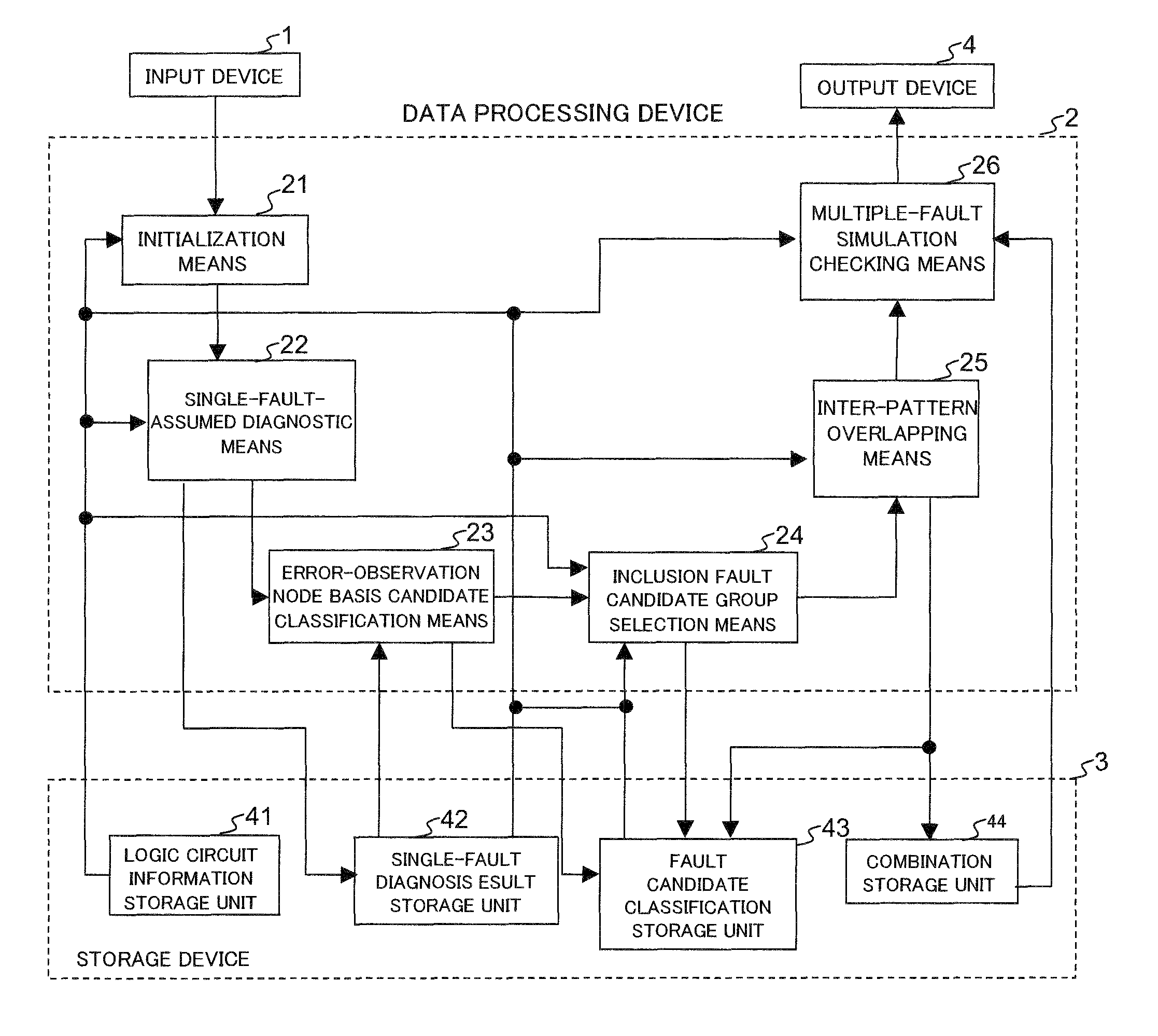
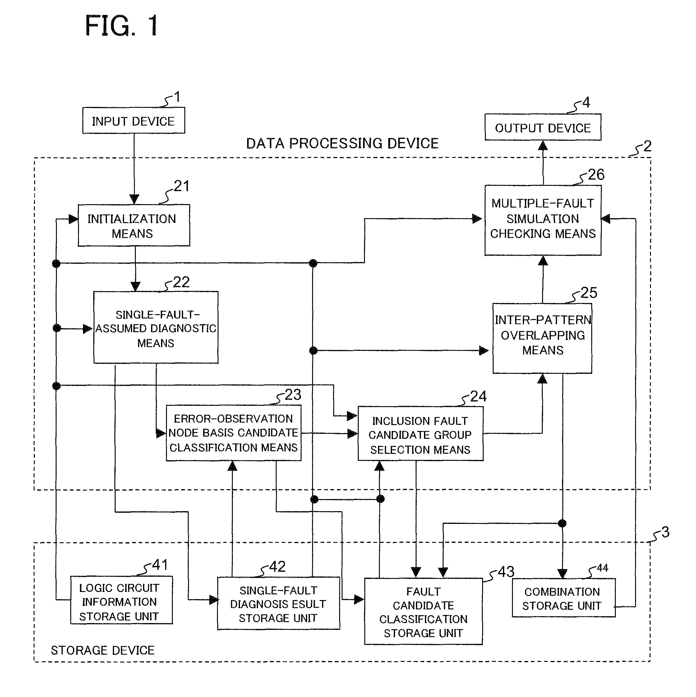
[0135]Next, preferred modes of the present invention will be described in detail with reference to the drawings. FIG. 1 is a diagram showing the configuration of a first example of the present invention. Referring to FIG. 1, the first example of the present invention comprises an input device 1 that has a keyboard or an external interface unit, a data processing device 2 that operates under program control, a storage device 3 such as a hard disk or a memory where information is stored, and an output device 4 such as a display or a printer that is an external interface unit.

[0136]The storage device 3 comprises a logic circuit information storage unit 41, a single-fault diagnosis result storage unit 42, a fault candidate classification storage unit 43, and a combination storage unit 44.

[0137]The logic circuit information storage unit 41 stores the following information:

[0138]logic states of signal lines being processed;

[0139]logic states (expected values) of signal lines when the circ...


PUM


Abstract

A fault location estimation system includes single-fault-assumed diagnostic unit nodes; error-observation node basis candidate classification unit; inclusion fault candidate group selection unit; inter-pattern overlapping unit; and multiple-fault simulation checking unit.

Description

REFERENCE TO RELATED APPLICATION[0001]The present application is claiming the priority of the earlier Japanese patent application No. 2006-274031 filed on Oct. 5, 2006, the entire disclosure thereof being incorporated herein by reference thereto.FIELD OF THE INVENTION[0002]The present invention relates to a multiple-fault location estimation system for estimating multiple fault locations speedily and accurately in a logic circuit.BACKGROUND OF THE INVENTION[0003]As one of conventional fault location estimation systems for multiple faults, reference is made to the fault location estimation system disclosed in Patent Document 1. This fault location estimation system estimates multiple fault locations in a logic circuit by grouping the related internal nodes for each error-observation node where a fault is detected during the test of the logic circuit, performing a single-fault-assumed fault simulation for each internal node, and finding a combination that accounts for entire error out...

Claims


Application Information

Patent Timeline
Patent Type & Authority Patents(United States)
IPC IPC(8): G01R31/28G06F11/30G06F11/00G01R31/26G01R31/08G01R31/00
CPCG01R31/318342G06F11/261
Inventor FUNATSU, YUKIHISA
Owner RENESAS ELECTRONICS CORP
Features
  • R&D
  • Intellectual Property
  • Life Sciences
  • Materials
  • Tech Scout
  • Unparalleled Data Quality
  • Higher Quality Content
  • 60% Fewer Hallucinations
Learn More