Thermal management system and method for automotive vehicle

a technology for automotive vehicles and management systems, applied in domestic cooling devices, lighting and heating devices, transportation and packaging, etc., can solve the problems of limiting the system's ability to transfer heat from coolant flowing through the downstream heat exchangers, and reducing the capacity to absorb hea

Active Publication Date: 2010-12-07
FORD GLOBAL TECH LLC
View PDF15 Cites 42 Cited by
  • Summary
  • Abstract
  • Description
  • Claims
  • Application Information

AI Technical Summary

Benefits of technology

[0007]According to another aspect of the present invention, a system controller may control the amount of heat rejected by a vehicular HVAC heat exchanger by controlling the operating speed of an air conditioning compressor incorporated within the HVAC system. This method and system are equally applicable to both electrodrive and mechanically driven HVAC compressors, with the latter having a clutch interposed between the compressor and a source of mechanical power, such as an engine crankshaft or camshaft.
[0009]It is an advantage of a system and method according to the present invention that both electronic and mechanical hardware onboard a vehicle may be protected from heat-related failures, while preserving the vehicle's function.
[0010]It is a further advantage of a method and system according to the present invention that thermal rejection by a vehicle to the ambient may be managed, notwithstanding usage of a single cooling air inlet into the vehicle.
[0011]It is a further advantage of a system and method according to the present invention that heat exchangers and / or related vehicular cooling components such as motors and fans may be downsized because the maximum heat load imposed upon the heat exchangers is governed by a controller, as opposed to being an open-loop operation.

Problems solved by technology

There are at least two drawbacks to conventional automotive air-to-liquid heat exchange systems.
While promoting efficient operation of the HVAC system, a disadvantage of this arrangement resides in the fact that the heated air flowing from the HVAC condenser has a reduced capacity to absorb heat, thereby limiting the system's ability to transfer heat from coolant flowing through the downstream heat exchangers.

Method used


Image

  • Thermal management system and method for automotive vehicle
  • Thermal management system and method for automotive vehicle
  • Thermal management system and method for automotive vehicle

Examples


Embodiment Construction

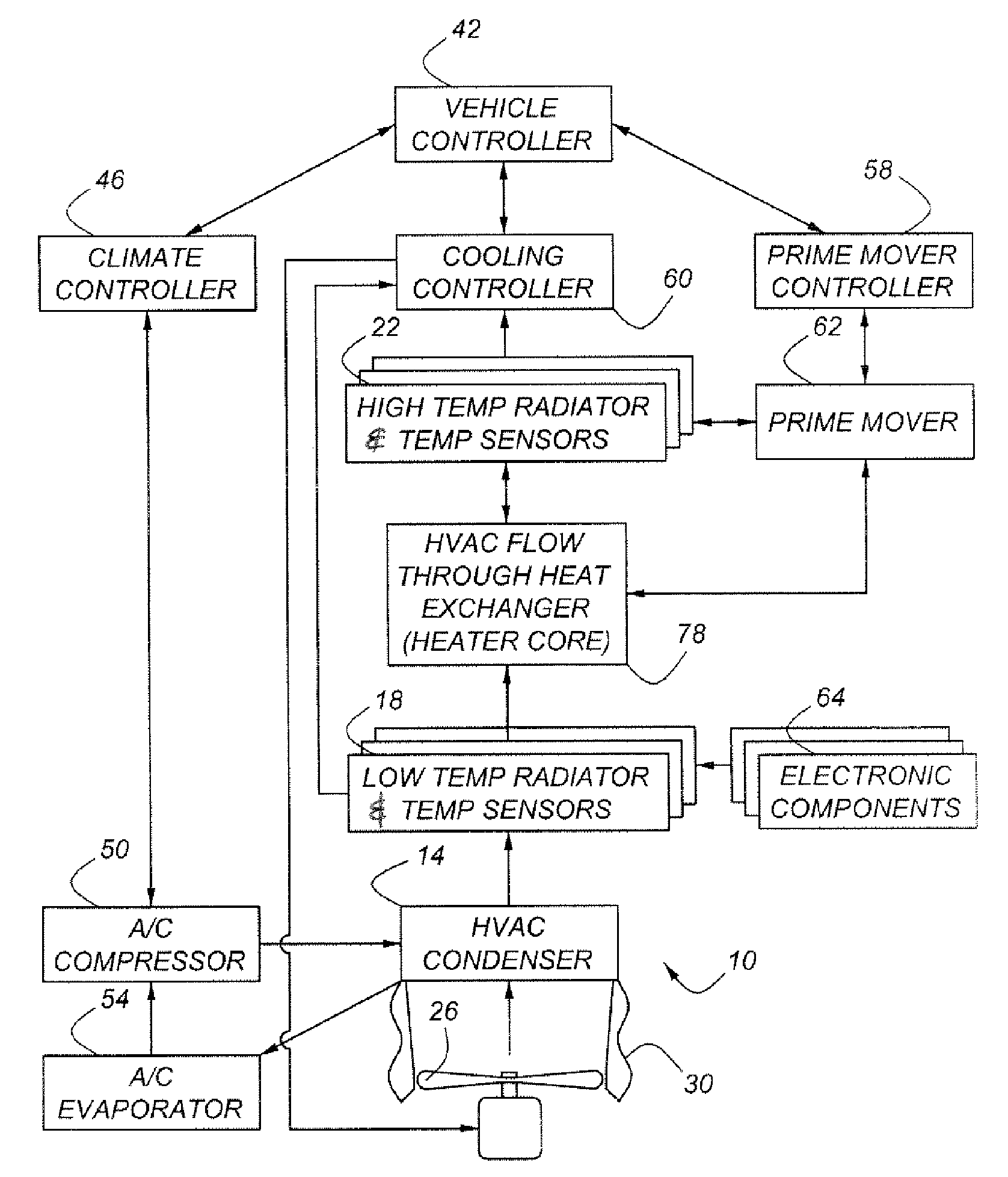
[0017]As shown in FIG. 1, a thermal management system, 10, for an automotive vehicle includes several air-cooled heat exchangers which are cooled serially by air forced by fan 26 through air intake duct 30. The first heat exchanger receiving outside air is HVAC exchanger 14. Air leaving heat exchanger 14 flows through low temperature radiator 18, which has temperature sensors associated therewith. Low temperature exchanger 18 is an electronics heat exchanger. Air having flowed through heat exchangers 14 and 18 then flows through heat exchanger 22, which is a high temperature radiator with temperature sensors. Heat exchanger, 22 is a prime mover heat exchanger for cooling an engine, a fuel cell, a battery pack, or other type of prime mover, including prime movers combining various ones of these elements.

[0018]HVAC condenser 14 receives compressed refrigerant vapor from AC compressor 50, which is equipped with associated temperature and pressure sensors (not shown). After the vapor ha...


PUM


Abstract

A thermal management system for an automotive vehicle includes air cooled heat exchangers for an HVAC system, for a prime mover, and for various electronics componentry. All heat exchangers are cooled by a common air stream flowing from the ambient. The amount of heat imparted to the air stream through the HVAC system is controlled as to permit optimal cooling of the vehicle electronics and vehicle prime mover.

Description

BACKGROUND OF THE INVENTION[0001]The present invention relates to an integrated system and method for managing heat rejection from not only a vehicle's prime mover and electronic componentry.[0002]The management of heat rejection from various vehicular systems, subsystems, and components has been the subject of much engineering effort since the dawn of the automotive age. Following earlier attempts at direct air cooling of prime movers, air-to-liquid heat exchangers became the dominant mechanism for rejecting waste heat from powertrains, whether based on conventional internal combustion engine technology, or hybrid technology, or other types of powertrains. Air-to-liquid heat exchangers are the preferred means for rejecting waste heat from vehicular heating, ventilating, and air conditioning (“HVAC”) systems, as well.[0003]There are at least two drawbacks to conventional automotive air-to-liquid heat exchange systems. In general, vehicular air conditioning condensers are usually loc...

Claims


Application Information

Patent Timeline
Patent Type & Authority Patents(United States)
IPC IPC(8): F25D23/12B60H1/32B60K11/00
CPCB60H1/00028B60H2001/00614B60H2001/00928
Inventor PATEL, UPENDRA J.SCHWARTZ, WILLIAM
Owner FORD GLOBAL TECH LLC
Why Eureka
Try Eureka