Transcritical refrigeration cycle

Active Publication Date: 2010-12-07
BITZER KUEHLMASCHINENBAU GMBH
View PDF30 Cites 19 Cited by
  • Summary
  • Abstract
  • Description
  • Claims
  • Application Information

AI Technical Summary

Benefits of technology

[0020]Thus, one embodiment of the invention consists of a transcritical vapour compression refrigeration system except that the single-stage reciprocating compressor, which is an essential component of the system, in the present invention, has some cylinders dedicated to the compression of refrigerant vapour being drawn from the evaporator to produce a refrigerating effect, and some cylinders dedicated to the compression of refrigerant vapour drawn from an economiser intermediate the first and second stages of expansion, to produce an increase of the refrigerating effect per unit mass of the refrigerant flowing through the evaporator
[0021]It is a surprising feature of the invention that, even when heat rejection is at transcritical pressures, the increase in refriger

Problems solved by technology

The system does not seem to have been a commercial su

Method used


Image

  • Transcritical refrigeration cycle
  • Transcritical refrigeration cycle
  • Transcritical refrigeration cycle

Examples


Example

Example

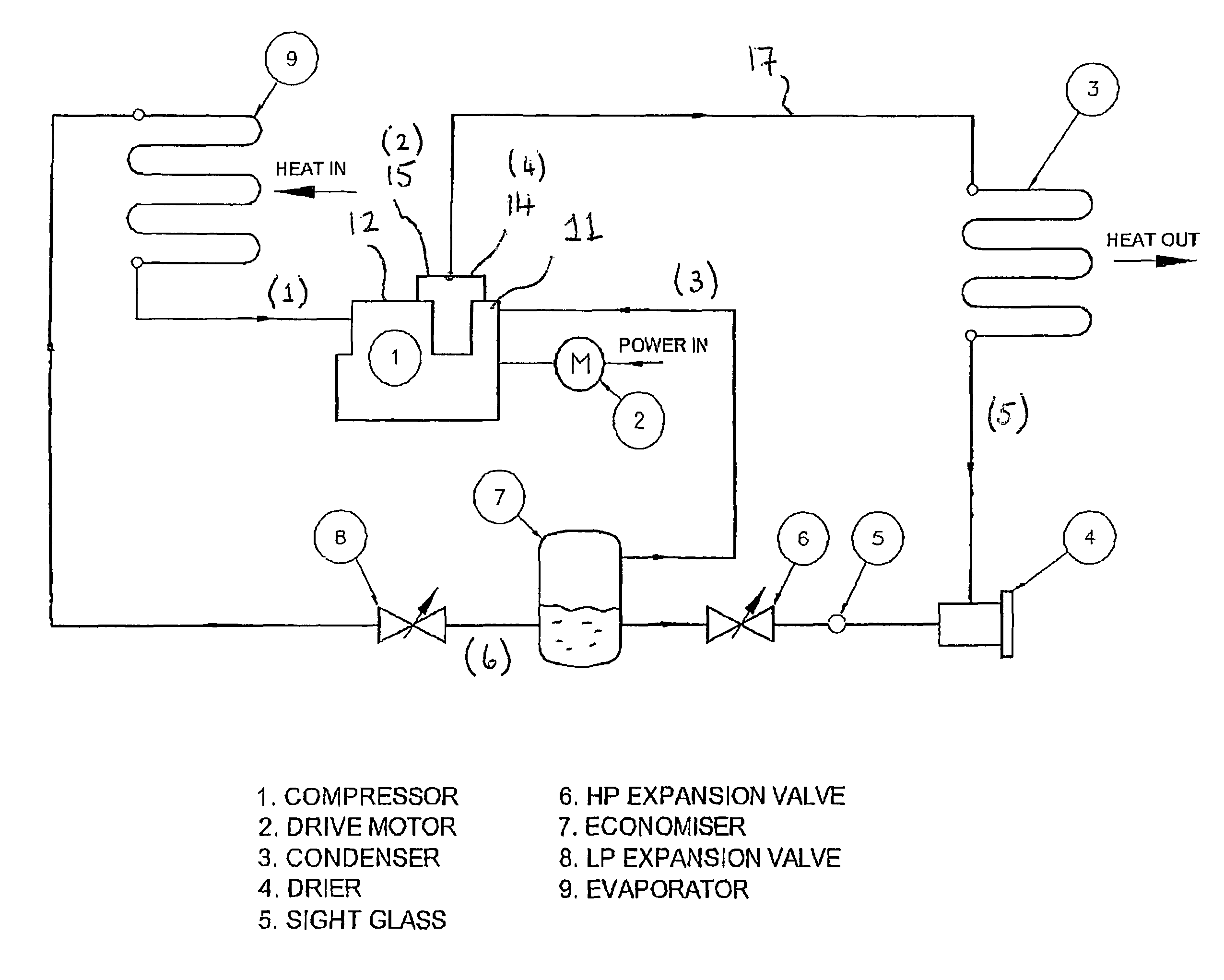
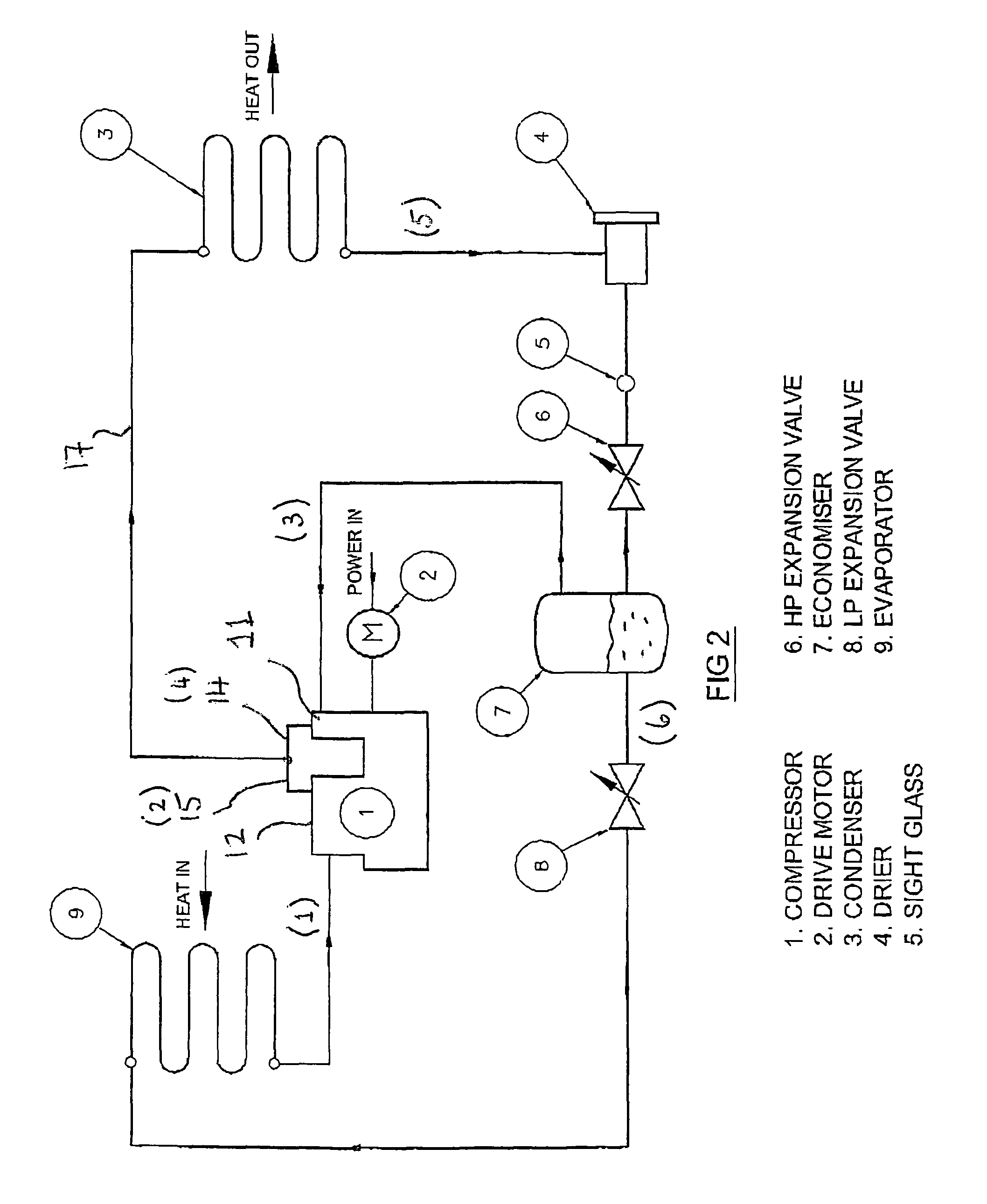
[0050]The method makes use of a single-stage, multi-cylinder, reciprocating compressor having two suction ports; one connected to the evaporator outlet and the other to an economiser designed to cool the main liquid flow. Compression of the two streams of refrigerant vapour takes place in parallel. The refrigerant streams do not mix until they reach discharge pressure at the compressor outlet.

[0051]Swept volumes associated with the individual suction connections are arranged to optimise performance at the intermediate pressure which gives highest efficiency.

Calculations

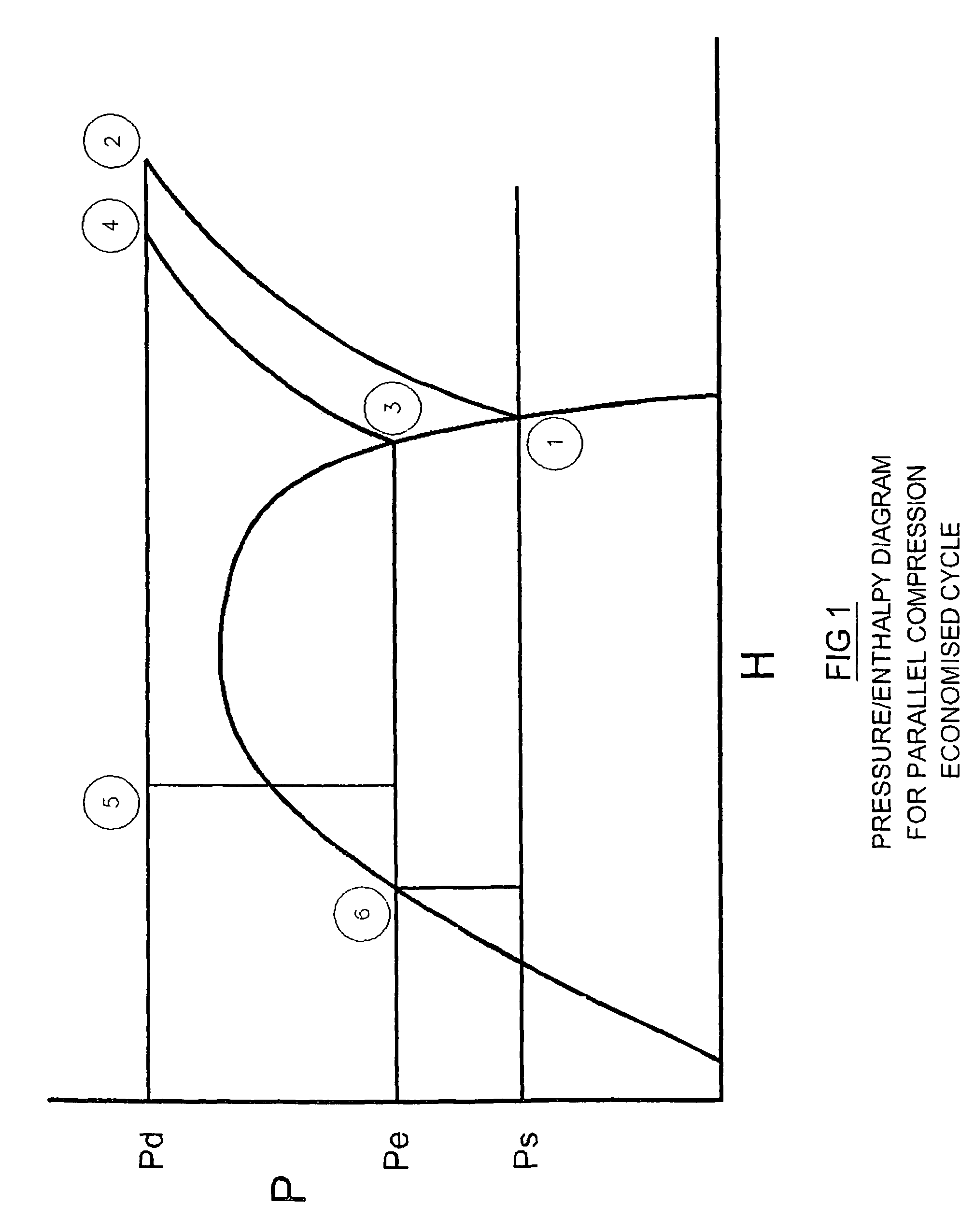
[0052]The following assumptions are made:[0053]Evaporating Temperature +5° C., equivalent to 40 Bar A.[0054]Heat rejection at a pressure of 90 Bar A.[0055]Supercritical discharge fluid cooled to 32° C. from discharge temperature.[0056]No superheating of suction vapour.[0057]Economising by evaporation of liquid refrigerant at econonomiser pressure but vapour produced is drawn into a separate compression process ...


PUM


Abstract

A transcritical vapour compression refrigeration apparatus including: a compressor, a gas cooler, an economiser, an evaporator and a refrigerant; the refrigerant being compressed in the compressor, heat being rejected from the compressed refrigerant at supercritical pressure in the gas cooler, the cooled compressed refrigerant being then expanded in a first stage to first temperature and pressure conditions in the economiser and then expanded in a second stage to second temperature and pressure conditions; a stream of refrigerant from the economiser at said first temperature and pressure conditions then being compressed in a first stream in the compressor, refrigerant at said second temperature and pressure conditions absorbing heat in the evaporator and then being compressed in a separate second stream in the compressor; said first and second compressed streams then being combined before passing to the gas cooler or passing through separate gas coolers before being combined.

Description

FIELD OF THE INVENTION[0001]The present invention relates to an improved transcritical vapour compression refrigeration system, apparatus and method, and a compressor for use in the apparatus.BACKGROUND OF THE INVENTION[0002]Vapour compression refrigerating systems can be arranged so that the condensed liquid refrigerant coming from the condenser at high pressure is sub-cooled to an intermediate temperature before being fed to an expansion device. Sub-cooling has the benefit of increasing the refrigerating effect per unit mass of the circulating refrigerant. This will improve the efficiency of the system provided the additional capacity produced is greater than the power increase required to produce it.[0003]Systems which use this effect include two-stage systems with intermediate cooling and liquid pre-cooling, two-stage systems without intercooling but with liquid pre-cooling (such systems are generally known as “economised” systems) and single-stage screw compressor systems which...

Claims


Application Information

Patent Timeline
IPC IPC(8): F25B1/00F04B25/00F25B1/02F25B9/00
CPCF25B1/02F25B9/008F25B2309/061F25B2400/074F25B2400/075F25B2400/13F25B2400/23
Inventor PEARSON, STEPHEN FORBES
Owner BITZER KUEHLMASCHINENBAU GMBH
Why Eureka
Try Eureka