Magnetoresistive sensor for determining an angle or a position

a magnetoresistive sensor and angle technology, applied in the field of magnetoresistive sensors, can solve problems such as increasing the occurrence of hysteresis areas

Active Publication Date: 2010-12-07
MEAS DEUTLAND
View PDF21 Cites 12 Cited by
  • Summary
  • Abstract
  • Description
  • Claims
  • Application Information

AI Technical Summary

Benefits of technology

[0003]In the case of the GMR effect and TMR effect, the resistance of a layer strip or of a tunnel transition is dependent on the angle β between the directions of the magnetization of two layers or layer components of magnetoresistive material. If the magnetization direction in the one layer component is fixed by means of a natural or artificial antiferromagnet which is in direct contact and only th...

Problems solved by technology

The continuous variation in the direction of the magnetization of the second component avoids the formation of domains both in the second component and (owi...

Method used


Image

  • Magnetoresistive sensor for determining an angle or a position
  • Magnetoresistive sensor for determining an angle or a position
  • Magnetoresistive sensor for determining an angle or a position

Examples


Embodiment Construction

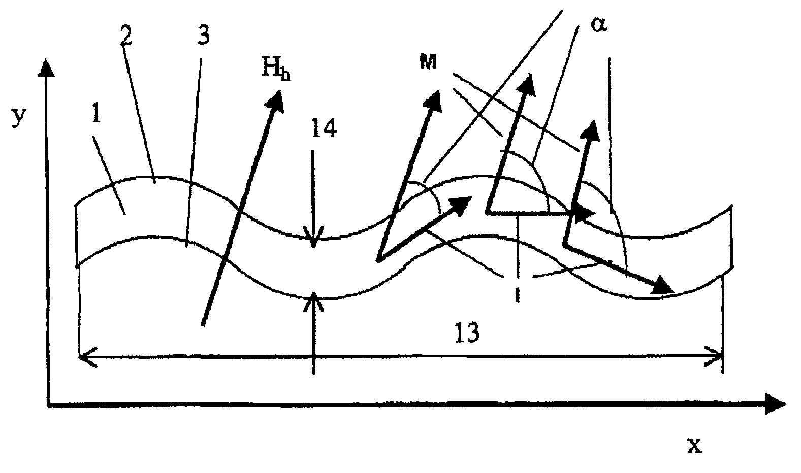
[0026]FIG. 1 illustrates the x-y layer plane of an AMR strip. The strip longitudinal direction is intended to coincide with the x axis in this case. The direction of the current I for a point on the strip is shown. In general, this direction does not match the strip longitudinal direction x. Under the influence of an external magnetic field, the magnetization M at the point under consideration points in the direction shown. The angle between the direction of the current I and the direction of the magnetization M is α. The resistivity ρa of the magnetoresistive layer is governed by this angle:

ρa(α)=ρa0+(Δρa / 2)(1−cos(2α))

[0027]where ρa0 is the non-field-dependent component and Δρa is the amplitude of the field-dependent change in the resistivity. The resistance-determining angle at any point on the strip is α. The resistivity is likewise a function of x when the direction of the current I and of the magnetization M varies in the strip longitudinal direction x.

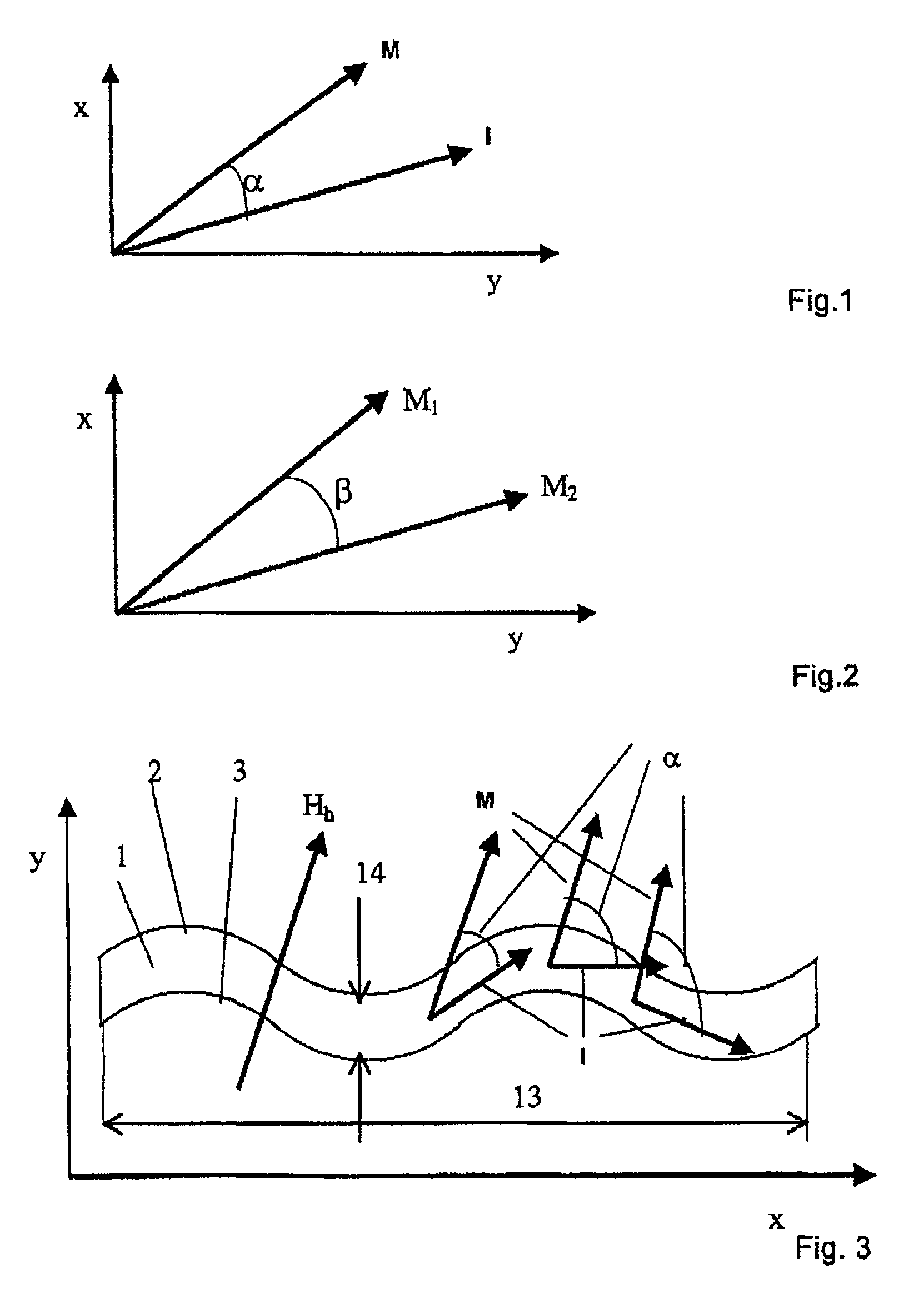
[0028]FIG. 2 shows a GMR ...


PUM


Abstract

Magnetoresistive sensors which use the AMR or the GMR effect and indicate the direction of the homogeneous magnetic field of a rotatable permanent magnet in the angle measurement or the position of the sensor with respect to a scale, which is magnetized periodically in an alternating direction, for the position measurement, and in which the angle or position value is obtained from the quotient of the output signals from two bridges or half bridges with the aid of arctan interpolation, allow small measurement errors if the output signals have small harmonic components and hysteresis areas. In arrangements according to the invention, this is achieved by the resistors being composed of strips and by continuously varying the resistance-determining angle along the strip longitudinal extent for each constant magnetic field acting on the strips. The resistance-determining angle is between the current and magnetization direction for AMR sensors and is between the magnetization directions of two layer components for GMR sensors.

Description

BACKGROUND OF THE INVENTION[0001]The invention relates to magnetoresistive sensors for determining angles which a rotatable magnet assumes with respect to the sensor, or of positions with the sensor being opposite a magnetic scale and having a periodic magnetic pattern. Such angle and position measurement arrangements are used in large numbers, for example in machine construction, in motor vehicle engineering and in precision mechanics.[0002]Magnetoresistive sensors for determination of angles or positions are known. The document WO 02 / 06845 A1 provides a summary of the prior art relating to analog determination of angles by means of magnetoresistive sensors on the basis of the anisotropic magnetoresistive (AMR) effect, the gigantic magnetoresistive (GMR) effect and the tunnel effect between magnetoresistive layers (TMR). In the case of the AMR effect, the resistance of a layer strip is governed by the angle α between the current direction and the direction of magnetization. This ca...

Claims


Application Information

Patent Timeline
IPC IPC(8): G01R33/12G01B7/30G01D5/14G01D5/16G01R33/09
CPCG01D5/145G01R33/09
Inventor BARTOS, AXELMEISENBERG, ARMINDETTMANN, FRITZ
Owner MEAS DEUTLAND
Why Eureka
Try Eureka