Yoke-type magnetic head and magnetic disk apparatus

a magnetic head and magnetic disk technology, applied in the field of magnetic head and magnetic disk apparatus therefor, can solve the problem that the magnetic head of the type with difficulty in determining a signal

Inactive Publication Date: 2010-12-07
KK TOSHIBA
View PDF11 Cites 1 Cited by
  • Summary
  • Abstract
  • Description
  • Claims
  • Application Information

AI Technical Summary

Benefits of technology

[0007]A general architecture that implements the various feature of the invention will now be described with reference to the drawings. The drawings and the associated descriptions are provided to illustrate embodiments of the invention and not to limit the scope of the invention.

Problems solved by technology

However, there has been a problem that the yoke-type magnetic head has difficulty in determining a signal due to Barkhausen noise.

Method used


Image

  • Yoke-type magnetic head and magnetic disk apparatus
  • Yoke-type magnetic head and magnetic disk apparatus
  • Yoke-type magnetic head and magnetic disk apparatus

Examples


first embodiment

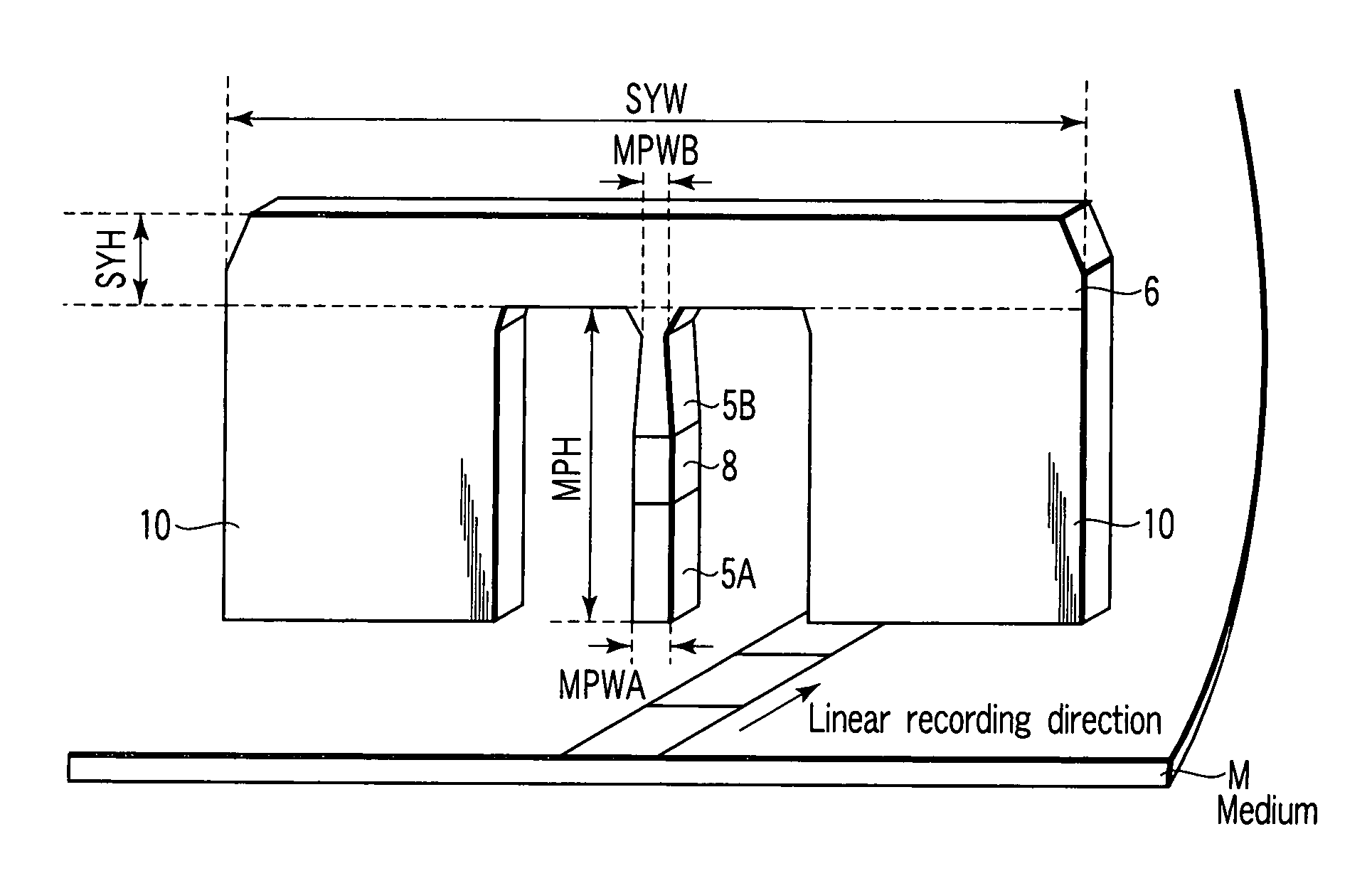
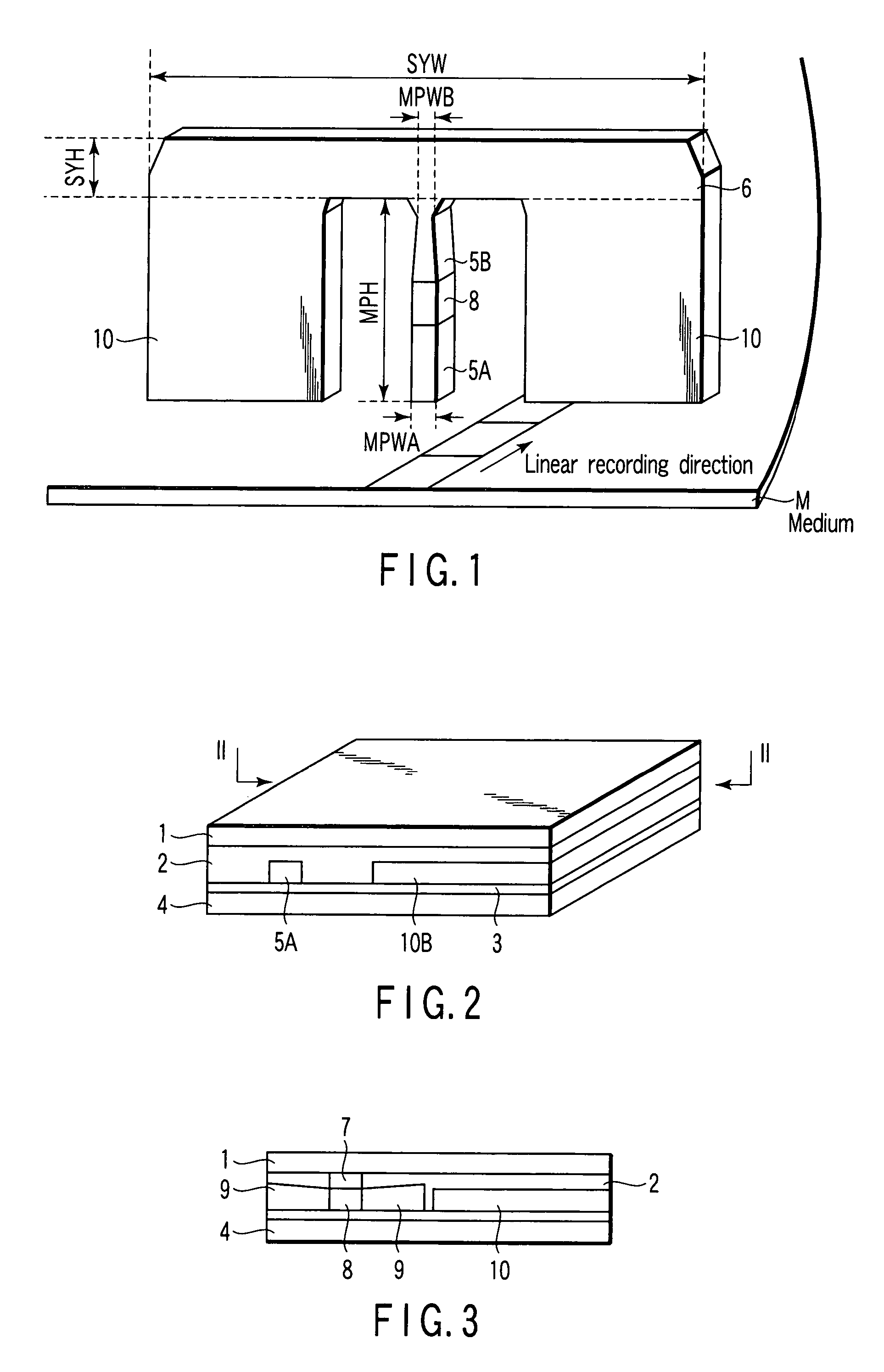
[0022]A configuration of a yoke-type reproducing magnetic head according to a first embodiment of the present invention will be described with reference to FIGS. 1, 2, and 3. FIG. 1 is a schematic view showing the magnetic head according to the first embodiment of the present invention. In addition, FIG. 2 is a perspective view showing a configuration of the magnetic head. FIG. 3 is a cross-sectional view of the magnetic head shown in FIG. 2 cut along the line II-II. In FIG. 2, a cross section on a front side in the figure shows an air bearing surface (ABS).

[0023]As shown in FIG. 1, main magnetic poles 5A and 5B which introduce a signal magnetic field from a medium in a magnetoresistance effect film, a sub yoke 6 for returning a magnetic field flowing into the main magnetic poles, and a side shield 10 are formed in a plane perpendicular to a linear recording direction of the medium. That is, the sub yoke 6 is formed in an off-track direction with respect to the main magnetic poles 5...

second embodiment

[0053]A second embodiment of the present invention has a structure in which the side shield is formed only on one side of the main magnetic pole, as shown in FIG. 12. In this case as well, as compared with the structure shown in FIG. 1, there is a lower degree of freedom in design, however, almost equivalent effect can be obtained.

third embodiment

[0054]A third embodiment of the present invention is characterized in that the main magnetic pole itself is made of a magnetization free layer of the magnetoresistance effect film in FIG. 5. In this manner, a magnetic flux flowing efficiency can be further increased. In this case, a rear part of the main magnetic pole may abut and is bonded with another magnetic layer, or the entire main magnetic pole as far as the return yoke may be made of the magnetization free layer. In addition, this structure is applicable to the structure shown in FIGS. 6A and 6B, or can obtain an advantageous effect by the structure shown in FIG. 7.

[0055]In the examples shown above, the structures in which the side shield is formed on sides of the main magnetic poles 5A and 5B are shown. However, as shown in FIG. 13, the side shield may not be formed.


PUM

PropertyMeasurementUnit
degree of freedomaaaaaaaaaa
magnetic informationaaaaaaaaaa

Abstract

According to one embodiment, a yoke-type magnetic head for reading out magnetic information from a medium in which information is magnetically recorded in a track direction, the head includes a magnetic pole which is provided on a plane perpendicular to a linear recording direction and has an opposing surface facing the medium, a saturation magnetic flux density Bs1, and a volume V1, a sub yoke which is formed on the plane by being connected to the magnetic pole, and has a length SYW in a direction perpendicular to the linear recording direction longer than a length SYH in a direction perpendicular to a surface of the medium, and a saturation magnetic flux density Bs2 and a volume V2, the product Bs2V2 of which is larger than the product Bs1V1, and a magnetoresistance effect film which is formed between the sub yoke and the opposing surface, and abuts the magnetic pole.

Description

CROSS-REFERENCE TO RELATED APPLICATIONS[0001]This application is based upon and claims the benefit of priority from Japanese Patent Application No. 2006-182424, filed Jun. 30, 2006, the entire contents of which are incorporated herein by reference.BACKGROUND[0002]1. Field[0003]One embodiment of the invention relates to a yoke-type magnetic head and a magnetic disk apparatus therefor.[0004]2. Description of the Related Art[0005]A next-generation magnetoresistance effect element faces problems such as a narrowed gap and a free layer soft magnetic properties, while a resistance change rate has been improved. In order to solve these problems, a yoke-type magnetic head has been proposed (Jpn. Pat. Appln. Publication No. 2001-256608).[0006]However, there has been a problem that the yoke-type magnetic head has difficulty in determining a signal due to Barkhausen noise.BRIEF DESCRIPTION OF THE SEVERAL VIEWS OF THE DRAWINGS[0007]A general architecture that implements the various feature of t...

Claims


Application Information

Patent Timeline
Patent Type & Authority Patents(United States)
IPC IPC(8): G11B5/39
CPCB82Y25/00G01R33/093G11B5/02G11B5/39H01L43/08G11B5/1276G11B2005/0002H10N50/10
Inventor KOUI, KATSUHIKO
Owner KK TOSHIBA
Why Eureka
Try Eureka