Controller of work piece-conveying robot

a controller and robot technology, applied in the direction of programme control, total factory control, instruments, etc., can solve the problems of robot hand movement in manual jog feed, robot hand movement may be moved, etc., to reduce the need for measuring instruments for setting the working area, reduce the need for manual jog feed operation, and easy to set

Active Publication Date: 2010-12-07
FANUC LTD
View PDF3 Cites 12 Cited by
  • Summary
  • Abstract
  • Description
  • Claims
  • Application Information

AI Technical Summary

Benefits of technology

[0009]It is an object of the present invention to provide a controller for a work piece conveying robot which is capable of preventing the switching of the manual jog feed coordinate system from being neglected or a wrong manual jog feed coordinate system from being set, and thus is capable of carrying out the robot teaching operation efficiently and safely.
[0019]In accordance with above construction, a current position of the robot hand is obtained by the hand position obtaining section, and since, if it is determined by the determination section that the robot hand is within the specified working area of the machine tool, a present manual jog feed coordinate system is automatically switched to a manual jog feed coordinate system assigned to the working area, failure to switch the manual jog feed coordinate system or setting of a wrong manual jog feed coordinate system can be prevented. If, during the manual jog feed operation of the robot hand, it is determined that the robot hand is within the specified working area, the robot operation is stopped and the present manual jog feed coordinate system is automatically switched to a manual jog feed coordinate system assigned to the working area, so that a manual jog feed coordinate system suitable for an accurate and safe teaching operation can be used at any time. Thus, an operator does not need switching manually the manual jog feed coordinate system during manual jog feed in teaching operation of the robot. Therefore, selection of a wrong unsuitable manual jog feed coordinate system can be eliminated, and the teaching operation can be carried out efficiently and safely.
[0021]When the specified working area is set to the machine tool based on the coordinate data, the need of the measurement instruments for setting the working area can be eliminated. When the working area is set based on the output data from photoelectric sensors, the working area can be easily set, and an alteration of the working area can be flexibly accommodated.
[0023]By making it possible to obtain a manual jog feed coordinate system assigned to the working area by communicating with the machine tool or peripheral devices, the coordinate system need not be stored in the controller, and a load imposed on the controller can be reduced. As a result, when the machine tool or the peripheral device is replaced, the controller can accommodate to the alteration flexibly.

Problems solved by technology

If the operator fails to switch the manual jog feed coordinate system and continues to use the manual jog feed coordinate system unsuitable to the working area to carry out the jog feed in the teaching operation, not only the motion of moving the robot hand in manual jog feed becomes complicated, but it may become sometimes necessary to go several points back to a teaching point and to switch the manual jog feed coordinate system and to do the manual jog feed operation over again.
If, in switching the manual jog feed coordinate system, a wrong manual jog feed coordinate system is selected, the robot hand may be moved in the manual jog feed in an undesired direction or to an undesired position.

Method used


Image

  • Controller of work piece-conveying robot
  • Controller of work piece-conveying robot
  • Controller of work piece-conveying robot

Examples


Embodiment Construction

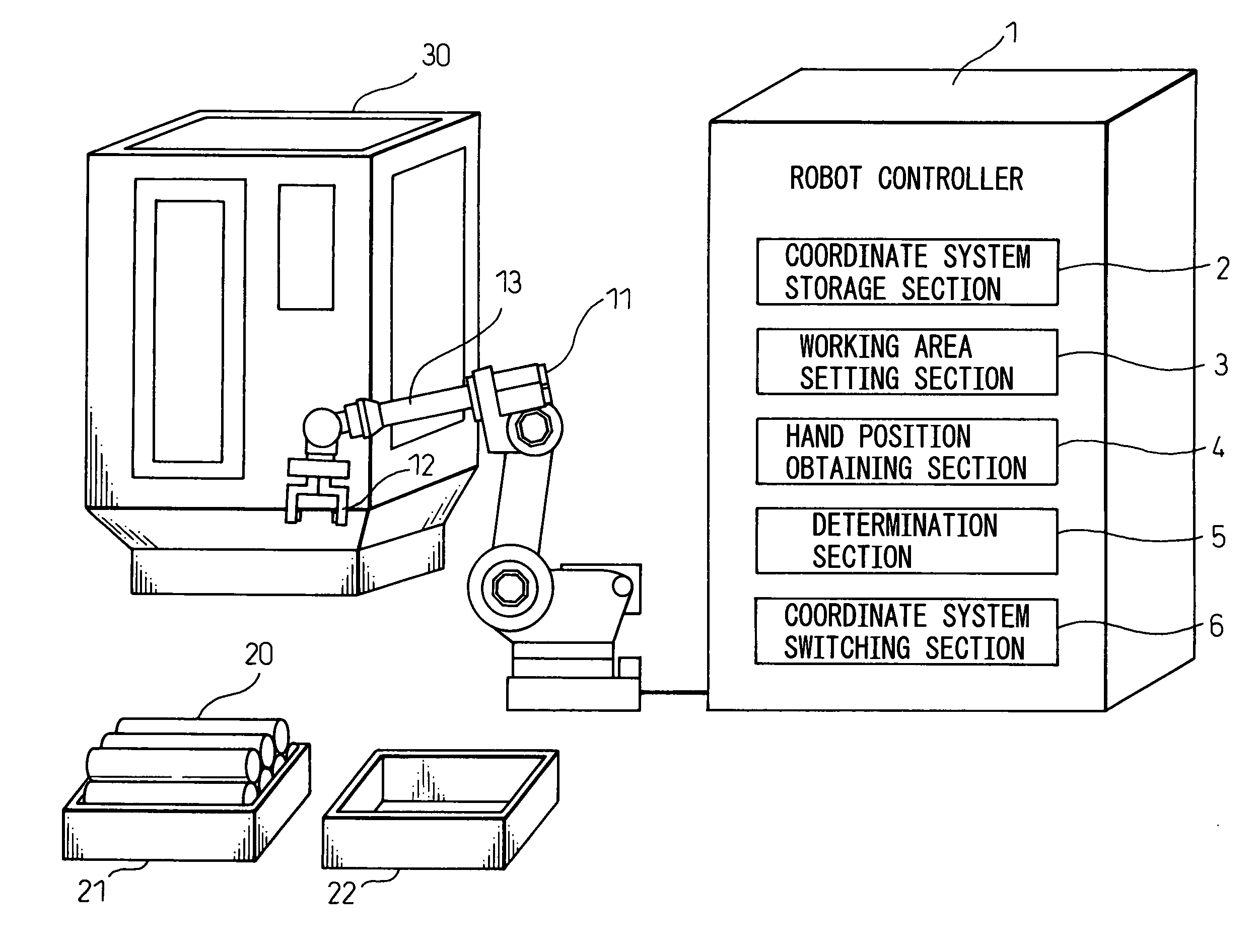
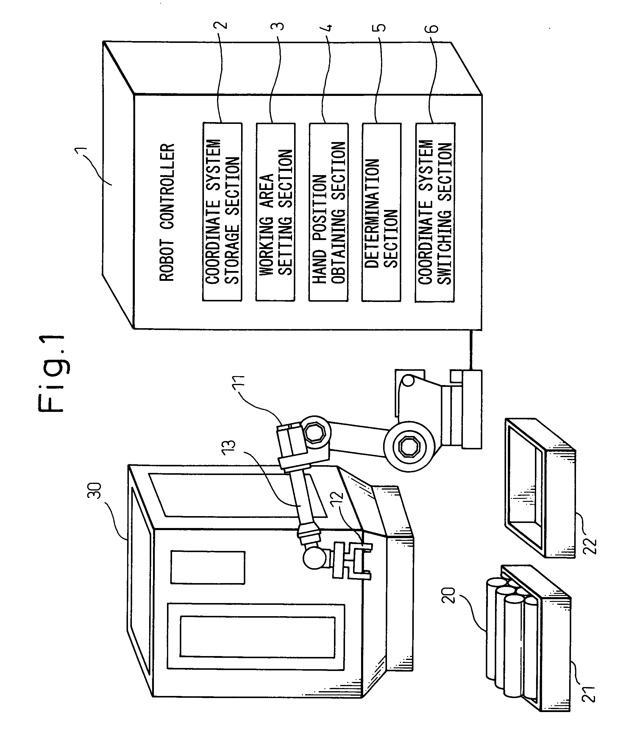
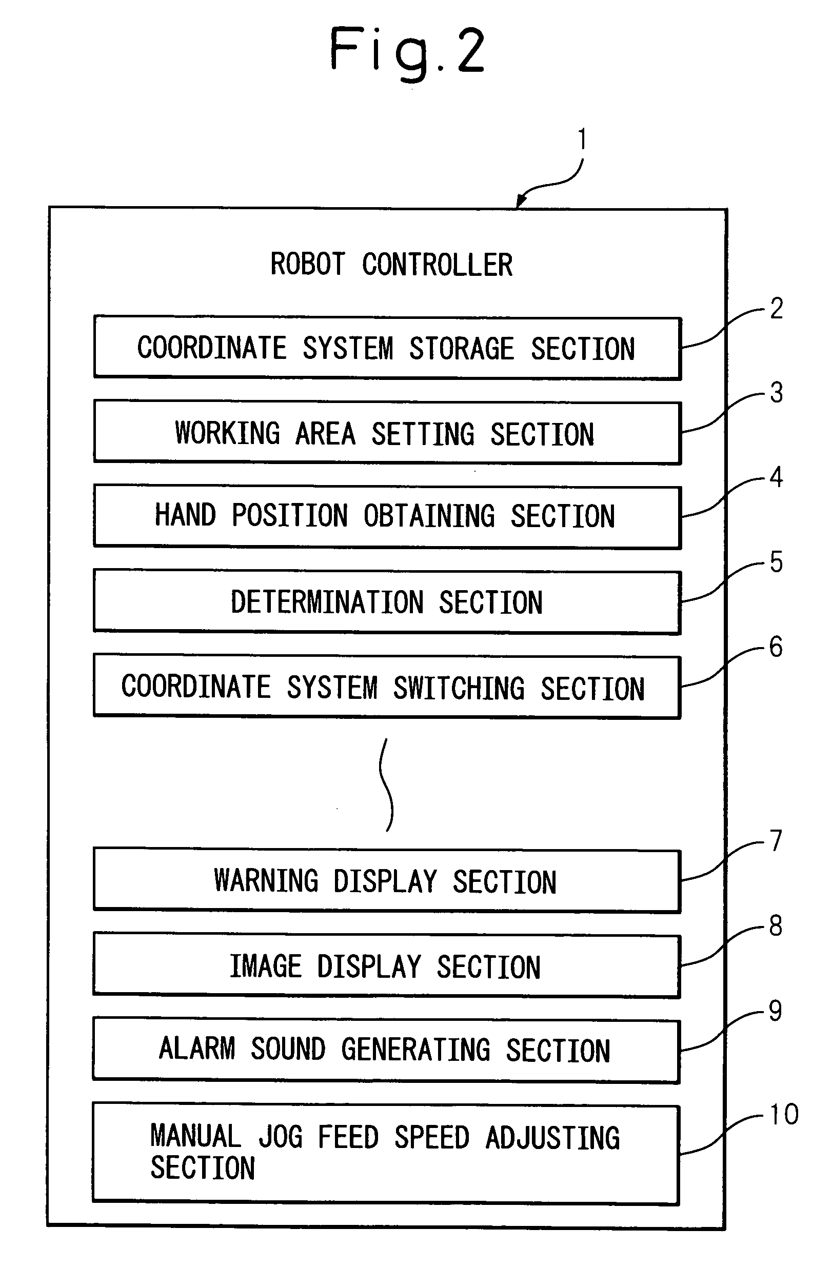
[0031]The present invention will be described in detail below with reference to drawings. FIG. 1 is a view for explaining a controller according to an embodiment of the present invention. Controller 1 of this embodiment is not particularly limited in this embodiment, but is directed to controlling work piece conveying robot 11 that conveys cylindrical work pieces 20 between palettes 21, 22 and machine tool 30. A processing system using a robot includes controller 1, robot 11, and machine tool 30.

[0032]Machine tool 30 is shown as a vertical type machining center having work table 31 (see FIG. 3), but is not particularly limited in type, as long as a 3-dimensional working area can be defined thereon, and thus may include a turning center or a press machine. Work piece 20 is grasped by robot hand 12, and is conveyed from palette 21 containing unprocessed work pieces to work table 31 of machine tool 30. After processing of work piece 20 is completed, work piece 20 is conveyed from work ...


PUM


Abstract

A controller for work piece-conveying robot having: a coordinate system storage section for storing one or more manual jog feed coordinate systems; a working area setting section for setting to a machine tool a working area to which the manual jog feed coordinate system is assigned; a hand position obtaining section for obtaining a current position of the robot hand at each specified sampling period; a determination section for determining whether or not the current position of the robot hand obtained by the hand position obtaining section is within the working area set by the working area setting section; and a coordinate system switching section for switching a present manual jog feed coordinate system to the manual jog feed coordinate system assigned to the working area if it is determined by the determination section that the current position of the robot hand is within the working area.

Description

CROSS REFERENCE TO RELATED APPLICATIONS[0001]The present application claims the benefit of priority based on Japanese Patent Application No. 2007-280638, filed on Oct. 29, 2007, disclosure of which is incorporated herein in its entirety by reference.BACKGROUND OF THE INVENTION[0002]1. Field of the Invention[0003]The present invention relates to a controller of a work piece-conveying robot for controlling the motion of a robot in supplying an unprocessed work piece to a machine tool or taking out a processed work piece from a machine tool.[0004]2. Description of Related Art[0005]In general, in a processing system using a robot comprising a numerically controlled machine tool and a robot provided with a robot hand for carrying out at least one of supplying and taking-out of a work piece to and from the numerically controlled machine tool, when a robot teaching operation is performed, a position is usually taught to the robot while a robot hand is being moved in a manual jog feed. In t...

Claims


Application Information

Patent Timeline
Patent Type & Authority Patents(United States)
IPC IPC(8): G05B15/00
CPCB25J9/1674G05B19/425G05B2219/39442G05B2219/39445Y02P90/02
Inventor NISHI, HIROJIIKEDA, YOSHITAKA
Owner FANUC LTD
Why Eureka
Try Eureka