Connecting system for surface coverings

a technology of connecting system and surface covering, which is applied in the field of surface covering, can solve the problems of difficult connection of the other side edges of the plank with another similar plank, adhesive can be pressed out of the seams, and the prior proposed floor system has suffered from disadvantages, etc., to achieve excellent joint integrity in strength and water-sealability

Active Publication Date: 2010-12-14
MANNINGTON MILLS
View PDF80 Cites 21 Cited by
  • Summary
  • Abstract
  • Description
  • Claims
  • Application Information

AI Technical Summary

Benefits of technology

[0006]Another feature of the present invention is to provide a connecting system for flooring planks and other surface-coverings that do not require any connecting accessories such as an insert or spline or metal clip, and the like, and permits easy and fast installation and flexibility.
[0007]Still another feature of the present invention is to provide a surface-covering system that has significant improvements with respect to ease of installation at confined areas, and includes a foolproof installation design and technique.

Problems solved by technology

However, prior proposed floor systems have suffered from disadvantages.
One disadvantage experienced with prior proposed floor systems is that if each of the side edges of a plank includes a tongue or groove, once one of the side edges is connected to another similar plank, it is difficult to connect the other side edges of the plank with another similar plank without lifting portions of the connected flooring to create the necessary angle to connect the plank.
This problem particularly accentuates while installing a click system floor at very limited free space confined areas such as any corners of a room, under the door jamb or under closets or kitchen islands and the like, where there is no room for lifting portions of the connected flooring to create the necessary angle to connect the plank.
For example, the straight side edges that are connected to one another may not be water tight and could potentially slide open to form a gap.
If an adhesive is used, the adhesive can be pressed out of the seams to create messy seams.
However, the integrity of the system is questionable and there is difficulty in making such a joint.

Method used


Image

  • Connecting system for surface coverings
  • Connecting system for surface coverings
  • Connecting system for surface coverings

Examples


Embodiment Construction

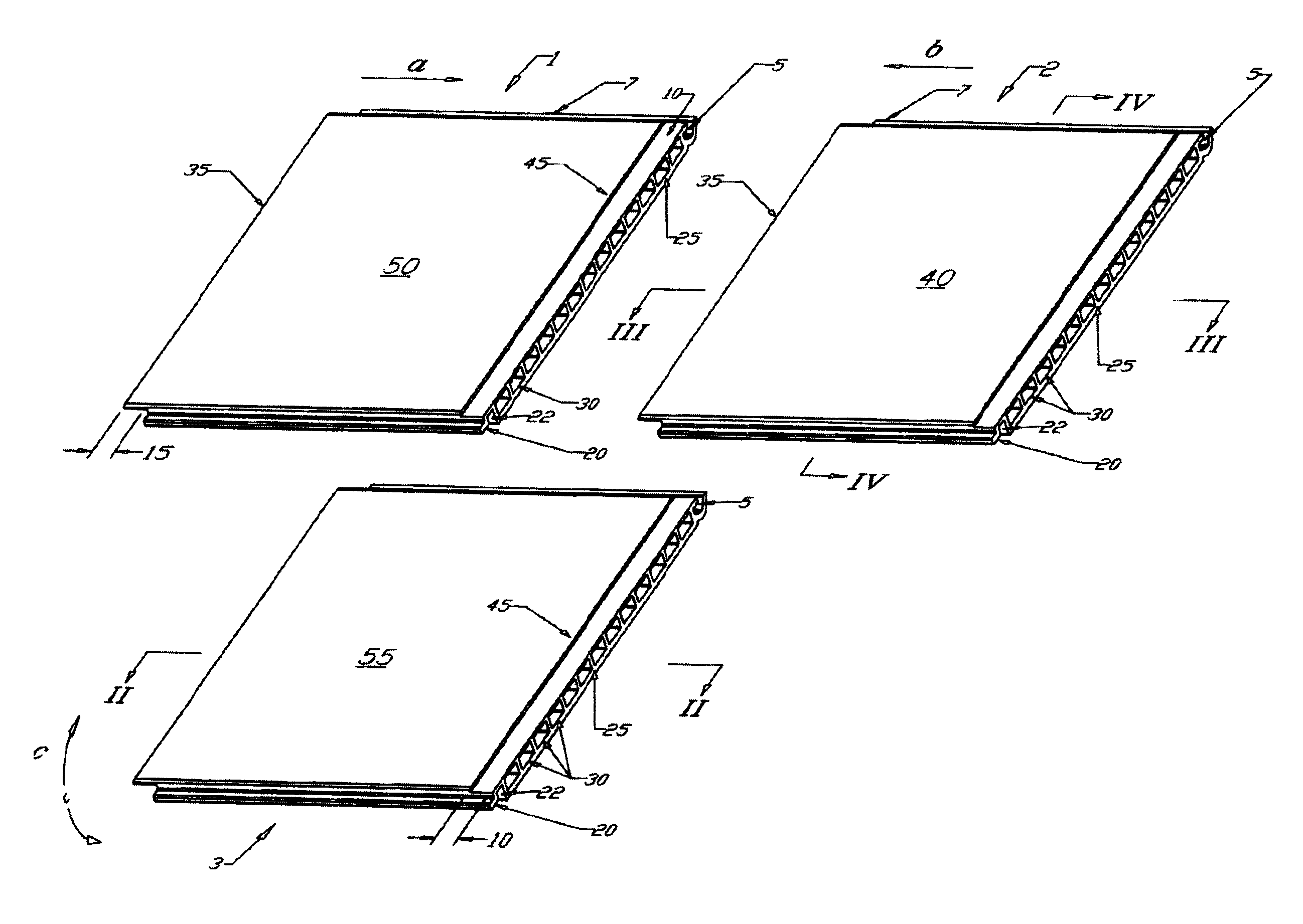
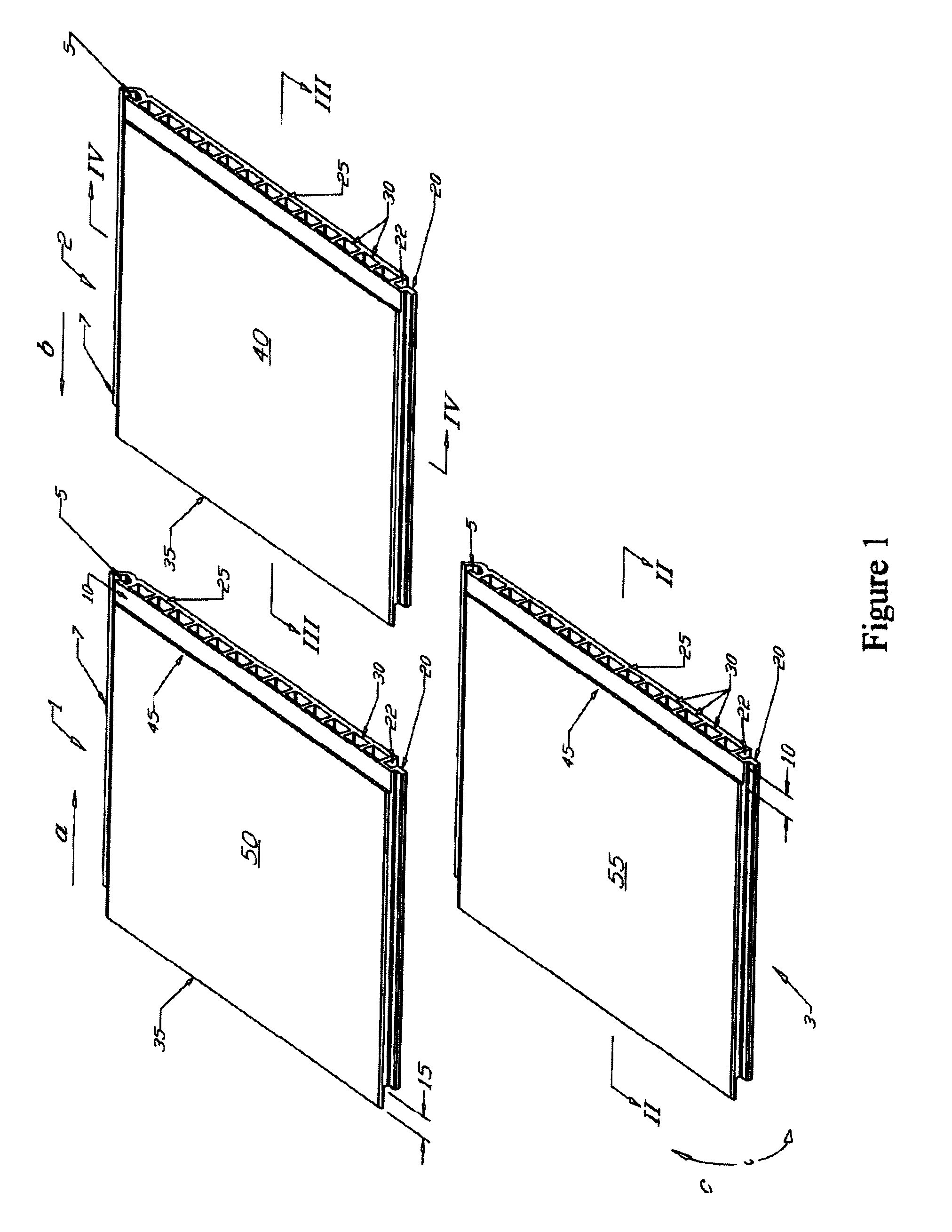
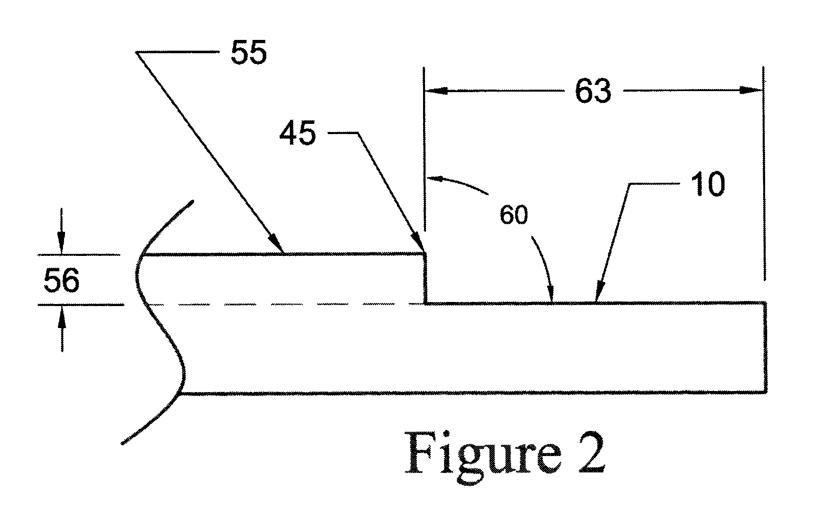
[0076]In general, the present invention relates to a surface covering system having a plank or a panel that includes a tongue along an edge of the plank and a mating groove along an edge opposite to the tongue. The plank can have a variety of designs on the other edges of the plank. For instance, the plank can include a shoulder along a third edge of the plank and a protruding lip extending along the fourth edge of the panel opposite from the third edge. The shoulder along one edge of one panel can be adapted to receive the protruding lip along an edge of a similar panel. A feature in one or more embodiments is to provide a panel or a plank comprising a groove defined, at least partially, by a first flange protruding from a first side of the plank along a first edge of the plank, and a second opposing flange protruding from a second, opposite side of the plank along the first edge. The first flange protruding from the first side of the plank can terminate at a distal first flange ed...


PUM

PropertyMeasurementUnit
outer angleaaaaaaaaaa
depthaaaaaaaaaa

Abstract

A system and method for joining floor planks includes two or more planks wherein each plank includes a tongue, a groove, and optionally a shoulder, and optionally a protruding lip, that provide a mechanism for connecting two or more planks together. The tongue can be on the opposing side of each plank from the groove. The groove can be defined between a first flange extending along a first edge of the plank and from one side of the plank, and a second flange extending distally beyond a distal edge of the first flange from the first edge of the plank and from a second side of the plank opposite from the first side. The tongue can be S-shaped to form an interlocking relationship with the groove.

Description

BACKGROUND OF THE INVENTION[0001]The present invention relates to surface-coverings, like flooring, and methods of installing the same.[0002]Various types of glueless mechanical locking systems (tongue and groove arrangements) have been utilized in the flooring industry. Flooring with glueless mechanical locking systems (tongue and groove arrangements) are becoming increasingly popular, as they are easy to lay, and, thus, it is not necessary to utilize highly trained personnel to lay such floor tiles.[0003]However, prior proposed floor systems have suffered from disadvantages. One disadvantage experienced with prior proposed floor systems is that if each of the side edges of a plank includes a tongue or groove, once one of the side edges is connected to another similar plank, it is difficult to connect the other side edges of the plank with another similar plank without lifting portions of the connected flooring to create the necessary angle to connect the plank. This problem partic...

Claims


Application Information

Patent Timeline
Patent Type & Authority Patents(United States)
IPC IPC(8): E04B5/00
CPCE04F13/18E04F15/10F16B5/0056F16B5/008E04F2201/0138E04F2201/0153E04F2201/028E04F2201/07E04F2203/04
Inventor CHEN, HAO A.WHISPELL, JOHN
Owner MANNINGTON MILLS
Why Eureka
Try Eureka