

Magnetic clamp
a technology of magnetic clamping and metal formwork, which is applied in the direction of electromagnets, electromagnets without armatures, mould fastening means, etc., can solve the problems of high process cost, imperfect surface of concrete members, and high labor intensity of steel beds, so as to increase the lateral shear capacity of the clamp and increase the friction coefficient
- Summary
- Abstract
- Description
- Claims
- Application Information
AI Technical Summary
Benefits of technology
Problems solved by technology
Method used
Image

Examples
first embodiment
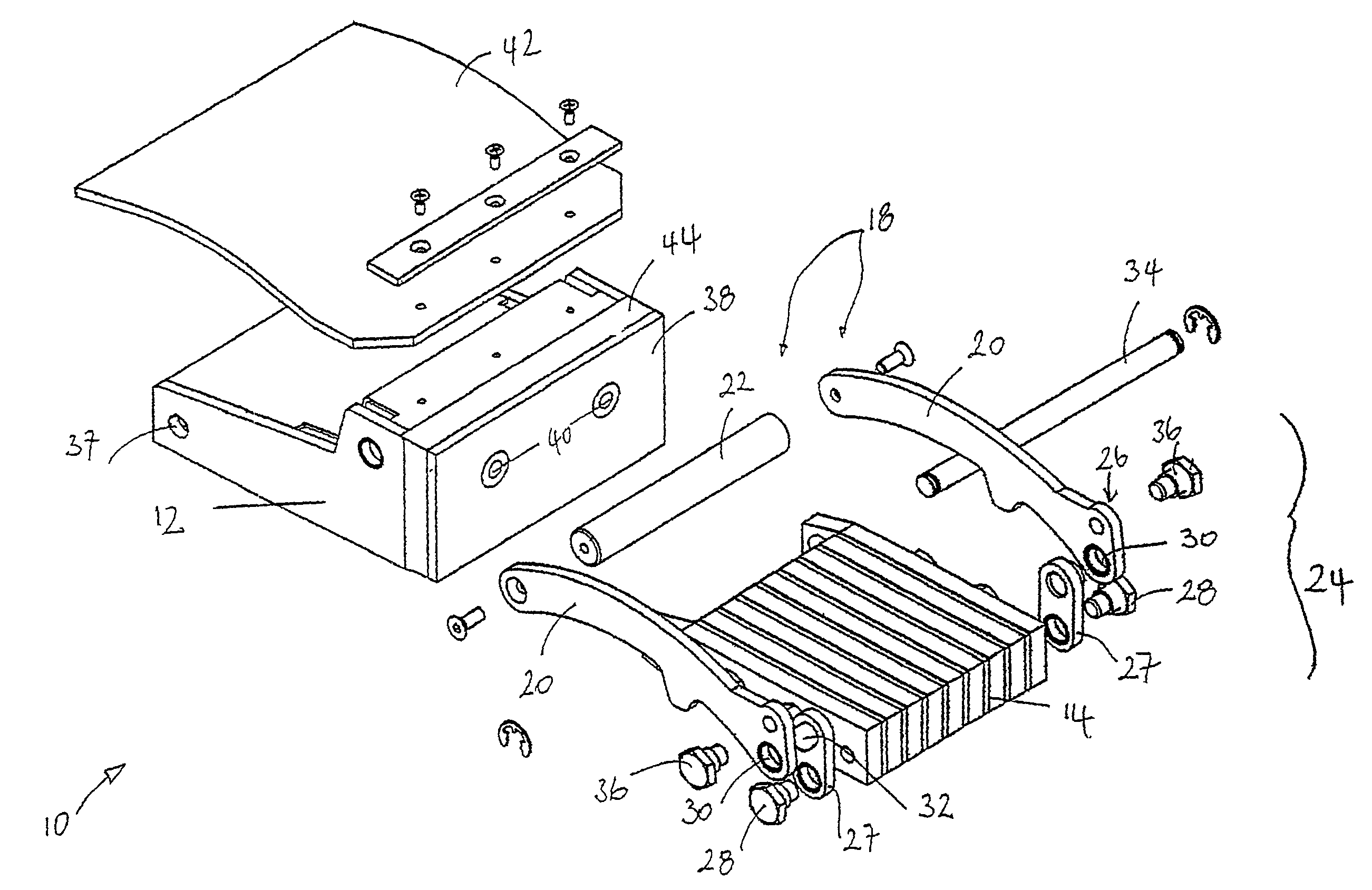
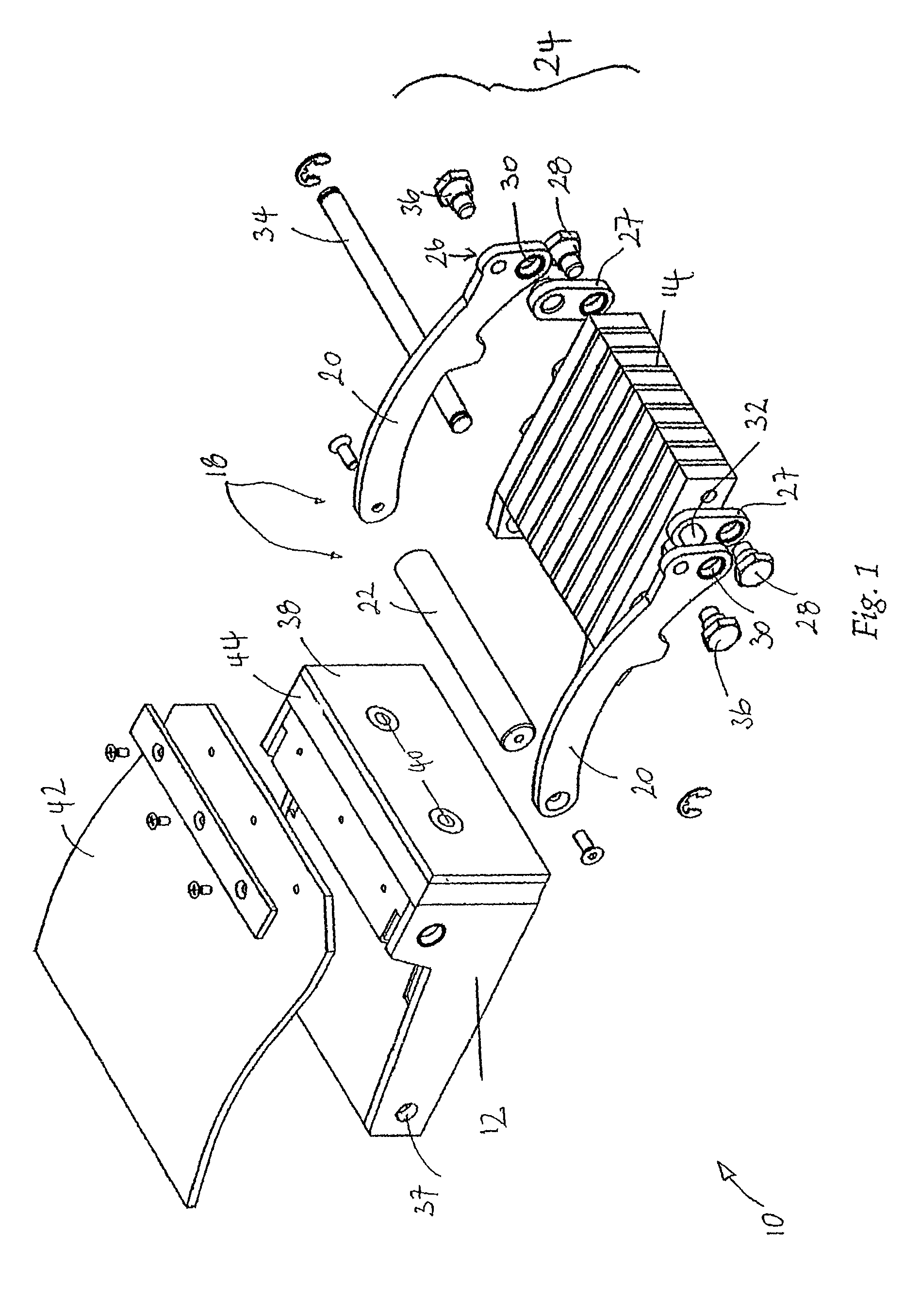
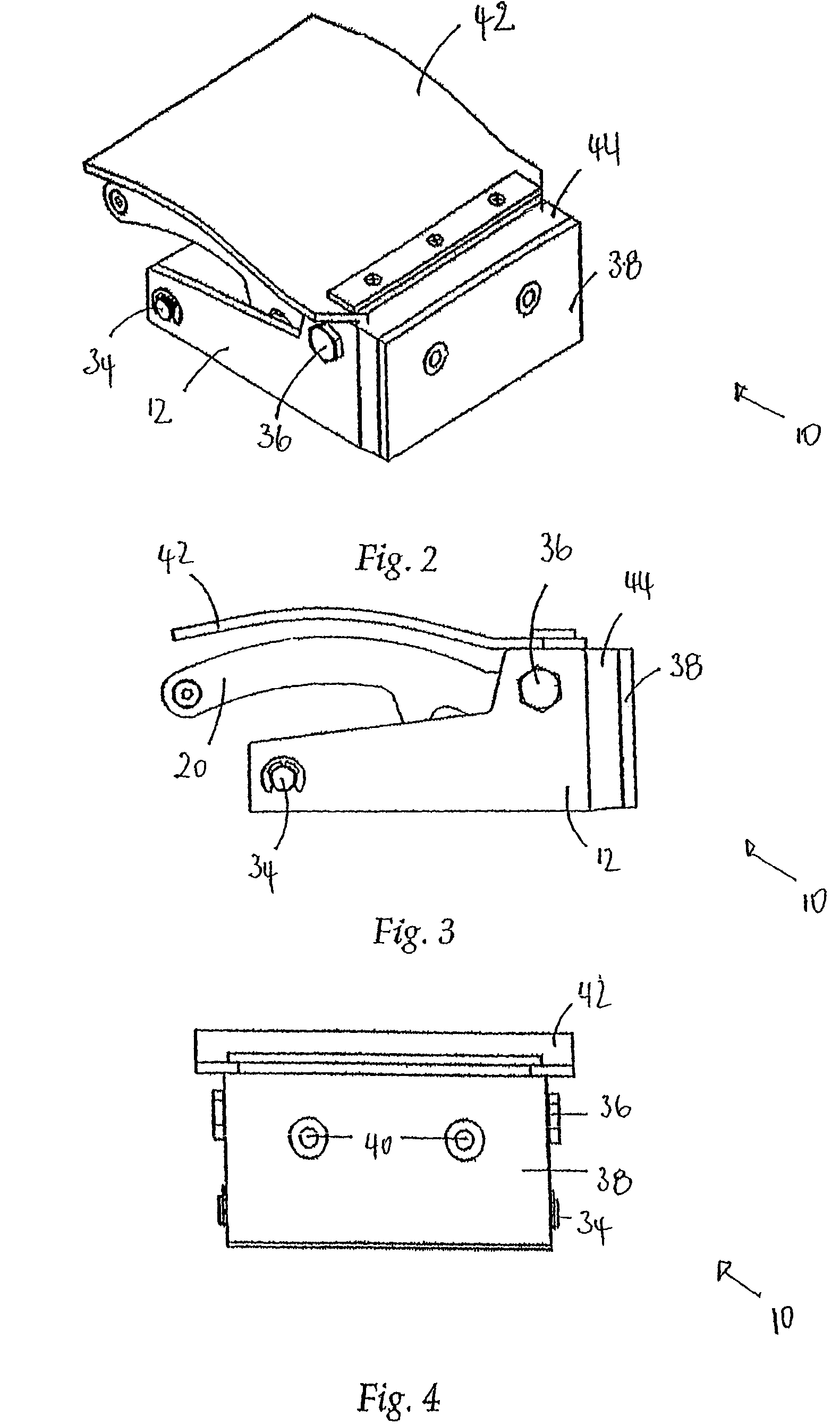
[0060]a magnetic clamp 10 for use in clamping metal formwork in precast concrete manufacture is illustrated in FIGS. 1 to 4 of the drawings. The clamp 10 includes a housing 12 and a magnet 14 received in the housing 12. The clamp 10 further includes a displacement mechanism in the form of an actuator handle 18 to displace the magnet 14 relative to the housing 12. The handle 18 includes a pair of lever arms 20 operable to move the magnet 14 between a first, disengaged position and a second, operative position in which the magnet 14 is substantially fully in contact with a magnetic bed (not shown in this embodiment) made of steel or other material capable of being attracted by a magnet used in the casting process. The lever arms 20 are pivotally connected at their first end to the housing 12 adjacent a first end of the housing 12. Free ends of the lever arms 20 are interconnected by a handle bar 22.
[0061]The clamp 10 further includes a force amplification mechanism 24 in the form of a...
second embodiment
[0070]a magnetic clamp 10 for use in clamping metal formwork in precast concrete manufacture is illustrated in FIGS. 5 to 19 of the drawings. With reference to FIGS. 1 to 4 of the drawings, like reference numerals refer to like parts unless otherwise specified. The force amplification mechanism 24 is in the form of a cam mechanism which performs a similar function to the linkage mechanism described above in relation to FIGS. 1 to 4.
[0071]The magnet 14 has two steel end plates 46 of which a section at the front is elevated extending above a top of the magnet 14. The raised section of each of the end plates 46 defines a horizontally extending slot 48, the slots 48 acting as a follower arrangement as will be described below. These horizontally extending slots 48 are parallel with the top of the magnet 14.
[0072]The magnet 14 is pivotally retained in the housing 12 by two pivot pins 50 received through pivot holes 52 in sides of the housing 12. The pins 50 are received in threaded holes ...
PUM
| Property | Measurement | Unit |
|---|---|---|
| force amplification | aaaaa | aaaaa |
| length | aaaaa | aaaaa |
| force | aaaaa | aaaaa |
Abstract
Description
Claims
Application Information