Method of manufacturing organic electroluminescence display apparatus

a technology of electroluminescence display and organic technology, which is applied in the field of manufacturing organic electroluminescence, can solve the problems of aging performed longer than needed to exceed the upper limit, the upper limit of the amount of change with elapsed time which is demanded for use, and the difficulty of estimation of the change in |dl/dt| due to aging at the maximum luminance during use, etc., to achieve the effect of preventing aging

Inactive Publication Date: 2010-12-14
CANON KK
View PDF8 Cites 3 Cited by
  • Summary
  • Abstract
  • Description
  • Claims
  • Application Information

AI Technical Summary

Benefits of technology

[0012]In view of the above-mentioned problem, the present invention provides a method of manufacturing an organic EL display apparatus, which is capable of preventing aging from being performed longer than needed to exceed an upper limit of the amount of a change with elapse of time at the maximum luminance, which is demanded for the use.
[0021]The present invention can suppress the rate of change in luminance per unit time when the organic EL device in the organic EL display apparatus is driven at a predetermined current or voltage after aging to a desired value or less. Therefore, the upper limit of the amount of change with elapse of time at the maximum luminance, which is demanded for the use, is achieved. At the same time, the aging can be prevented from being performed longer than needed to exceed the upper limit of the amount of change with elapse of time at the maximum luminance, which is demanded for the use.
[0022]In particular, a manufacturing method according to another aspect of the invention can make the rate of change per unit time substantially constant. Therefore, the aging can be performed at higher accuracy.

Problems solved by technology

Accordingly, there is fear that the upper limit of the amount of change with elapse of time at the maximum luminance, which is demanded for the use, is not achieved.
Therefore, there is fear that the aging is performed longer than needed to exceed the upper limit of the amount of change with elapse of time at the maximum luminance, which is demanded for the use.
As described above, when the aging is performed at a constant current applied to the organic EL device, the estimation of a change in |dL / dt| due to the aging at the maximum luminance during the use sometimes becomes difficult because the luminance of the organic EL device is not constant.
Therefore, when the luminance during the aging is lower than the luminance during the actual use, the completion of the aging cannot be determined because the change in luminance per unit time during the aging is larger than the change in luminance per unit time during the actual use.
Therefore, it is disadvantageously difficult to estimate an optimal luminance for aging in consideration of the change in luminance due to aging.

Method used


Image

  • Method of manufacturing organic electroluminescence display apparatus
  • Method of manufacturing organic electroluminescence display apparatus
  • Method of manufacturing organic electroluminescence display apparatus

Examples


embodiment 1

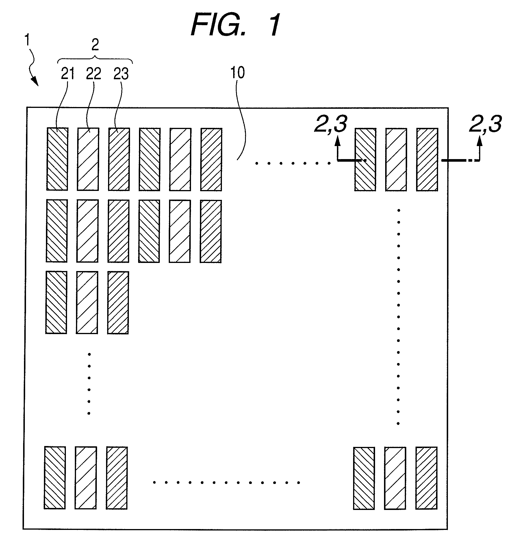
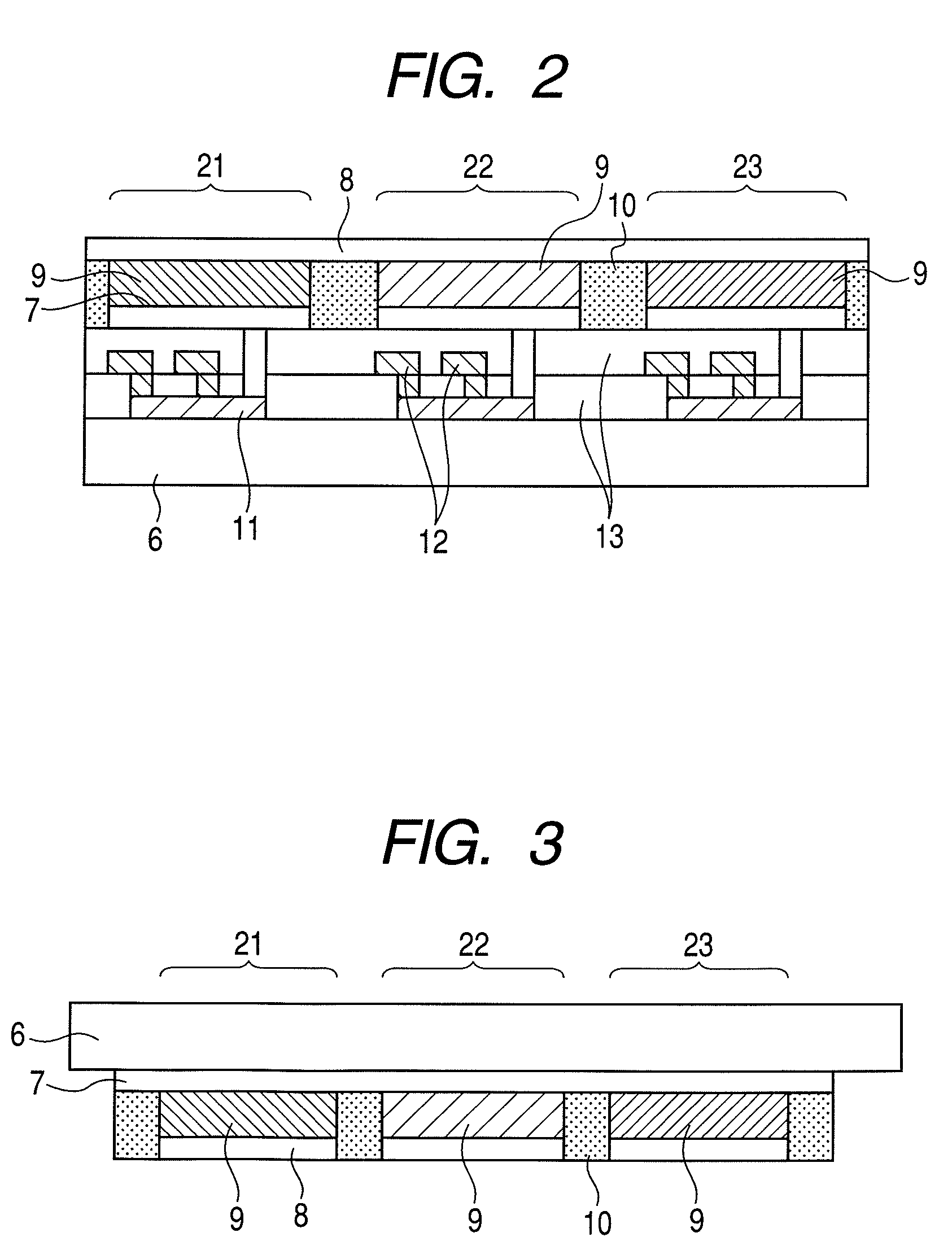
[0049]In this Embodiment 1, a current is applied to the organic EL devices 2 in the organic EL display apparatus 1 to cause the organic EL devices 2 to emit light at a constant luminance. The aging is performed until |d(log η) / dt| at the luminance falls within a predetermined range. When the organic EL devices 2 in the organic EL display apparatus 1 are caused to emit light at a predetermined luminance, the current efficiency of the organic EL devices 2 is lowered due to an increase in current density, which is caused with the deterioration of the organic EL devices 2. The decrease in current efficiency of the organic EL devices 2 is moderated, and |d(log η) / dt| gradually decreases. Then, when |d(log η) / dt| falls within a predetermined range, the aging is terminated. As a result, a rate of change in luminance per unit time when the organic EL devices 2 in the organic EL display apparatus 1 are driven at a predetermined current or voltage after the aging can be restrained to be equal...

embodiment 2

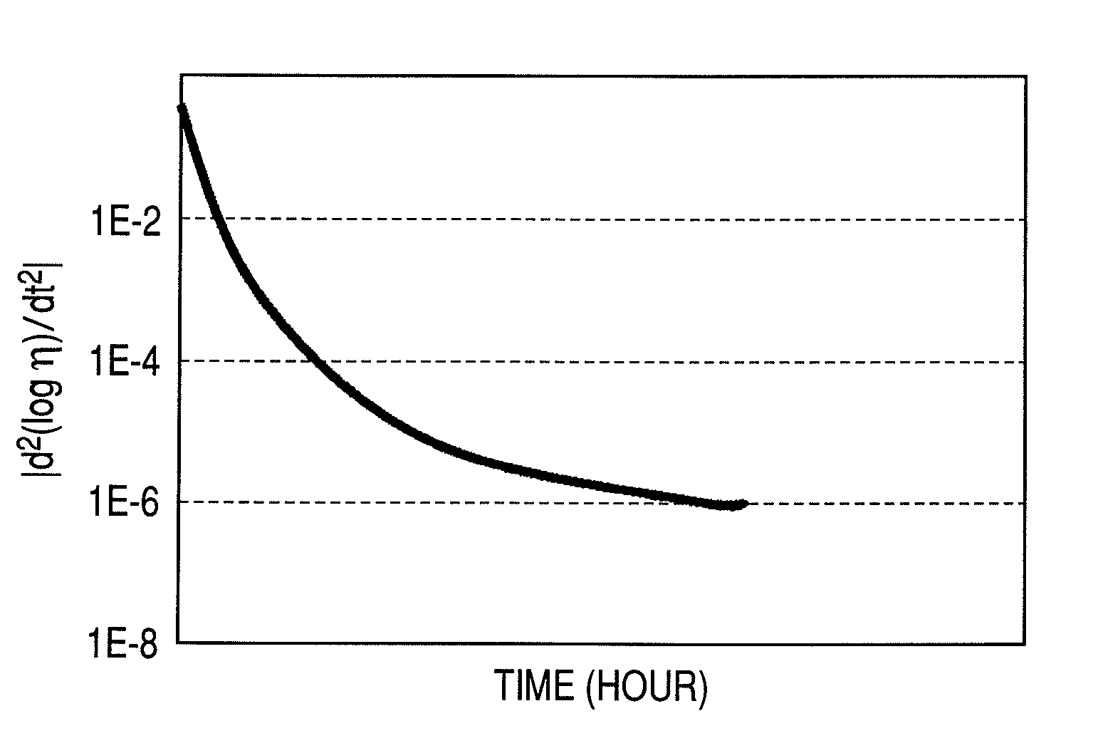
[0050]In this Embodiment 2, a current is applied to the organic EL devices 2 in the organic EL display apparatus 1 to cause the organic EL devices 2 to emit light at a constant luminance. The aging is performed until |d2(log η) / dt2 at the luminance falls within a predetermined range. When the organic EL devices 2 in the organic EL display apparatus 1 are caused to emit light at a predetermined luminance, the current efficiency of the organic EL devices 2 is lowered due to an increase in current density, which is caused with the deterioration of the organic EL devices 2. The decrease in current efficiency demonstrates a tendency to be rapid at the start of decrease and then be moderated. Correspondingly, |d2(log η) / dt2| gradually decreases in the aging process. Then, when |d2(log η) / dt2| falls within a predetermined range, the aging is terminated. As a result, a rate of change in luminance per unit time when the organic EL devices 2 in the organic EL display apparatus 1 are driven at...

embodiment 3

[0051]As a variation of Embodiment 1 or 2 described above, an aging method for measuring |d(log η) / dt| (|d2(log η) / dt2|) at predetermined time intervals is one of the preferred aging methods. In order to measure |d(log η) / dt| (|d2(log η) / dt2|), the current efficiency is required to be measured at least twice (three times). Therefore, when a set of at least two (three) consecutive measurements is regarded as one measurement period, the aging can be performed in an arbitrary step between the measurement periods. As a result, by arbitrarily combining steps having different aging effects, the aging for allowing the rate of decrease in luminance after the aging to fall within the range of the rate of decrease in luminance, which is demanded for the use, can be performed.


PUM


Abstract

Provided is a method of manufacturing an organic electroluminescence display apparatus including an organic electroluminescence device formed on a substrate, the organic electroluminescence device including a first electrode and a second electrode, at least one of which is transparent, and an organic emission layer formed between the first electrode and the second electrode, the organic emission layer being for emitting light by application of a current. Aging is performed until a rate of change in current efficiency of the organic electroluminescence device per unit time at a predetermined luminance or the amount of change per unit time in the rate of change in current efficiency of the organic electroluminescence device per unit time falls within a predetermined range.

Description

BACKGROUND OF THE INVENTION[0001]1. Field of the Invention[0002]The present invention relates to a method of manufacturing an organic electroluminescence (hereinafter, abbreviated as EL) display apparatus.[0003]2. Description of the Related Art[0004]Japanese Patent No. 3,250,561 discloses a method of manufacturing an organic EL display apparatus for performing so-called aging to suppress a change in luminance of the organic EL display apparatus with elapse of time. The aging is a treatment for applying a current between an anode and a cathode. According to the disclosed method, the aging for obtaining a curve of change in luminance with time, which is measured when an organic EL device is driven at a constant current, is first performed. Thereafter, the curve of change in luminance with time is analyzed to be divided into a component having a slowest luminance age-deterioration rate and other components. Then, the aging is conducted until a luminance becomes approximately equal to a...

Claims


Application Information

Patent Timeline
Patent Type & Authority Patents(United States)
IPC IPC(8): H01J9/20H01J9/42
CPCG09G3/3216G09G3/3225H01L27/3269G09G3/14G09G2320/0233G09G2320/043G09G2320/0693G09G2360/145H01L2251/562H10K59/13H10K71/831
Inventor UNO, YOSHINORIOKADA, NAOTO
Owner CANON KK
Why Eureka
Try Eureka