
Nano and meso shell-core control of physical properties and performance of electrically insulating composites

a technology of electrical insulation composites and shell cores, which is applied in the direction of chemistry apparatus and processes, transportation and packaging, synthetic resin layered products, etc., can solve the problems that most inorganic materials do not allow independent selection of structural characteristics, and achieve high thermal conductivity (htc), facilitate the transport of phonons, and reduce the effect of mean distances

Active Publication Date: 2010-12-14
SIEMENS ENERGY INC
View PDF155 Cites 5 Cited by
  • Summary
  • Abstract
  • Description
  • Claims
  • Application Information

AI Technical Summary

Benefits of technology

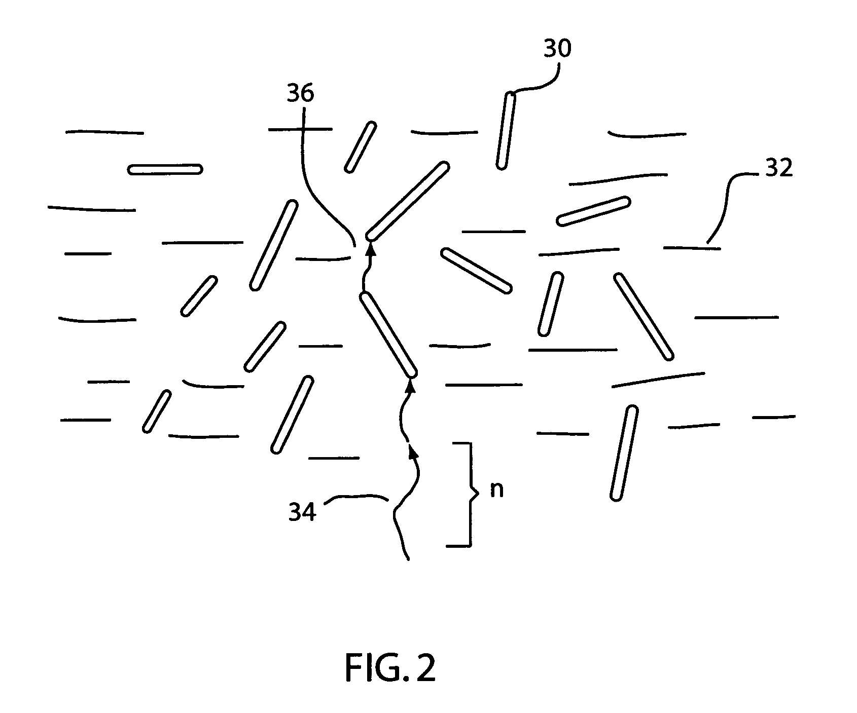
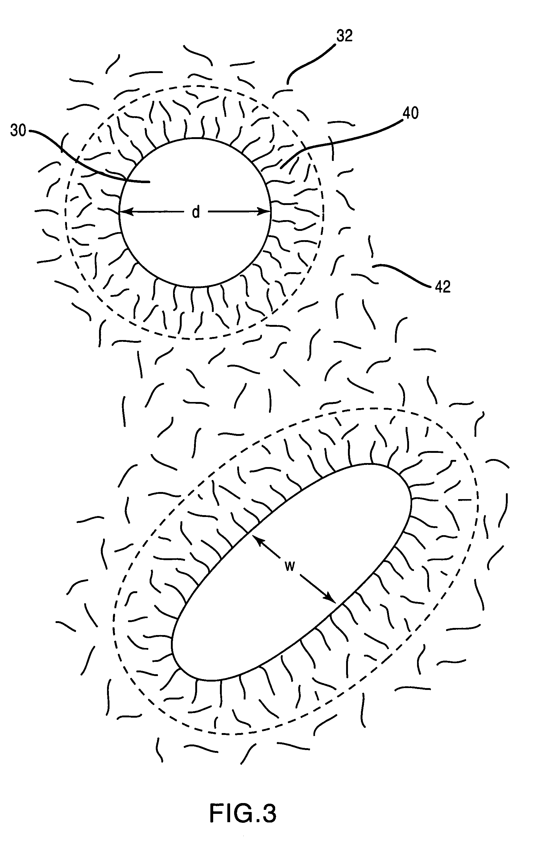
[0009]With the foregoing in mind, methods and apparatuses consistent with the present invention, which inter alia facilitates the transport of phonons through a high thermal conductivity (HTC) impregnated medium to reduce the mean distances between the HTC materials below that of the mean phonon path length. This reduces the phonon scattering and produces a greater net flow or flux of phonons away from the heat source. In addition the HTC materials impart a degree of ordering on the surrounding resin structure. This creates an ordered resin shell (ORS) around the HTC materials. The ORSs created in this manner can be manipulated through HTC concentration and clustering to create overlapping areas of ORSs that reduce the scattering of phonons passing through them. The resins may be part of a host matrix medium, such as a multi-layered insulating tape.
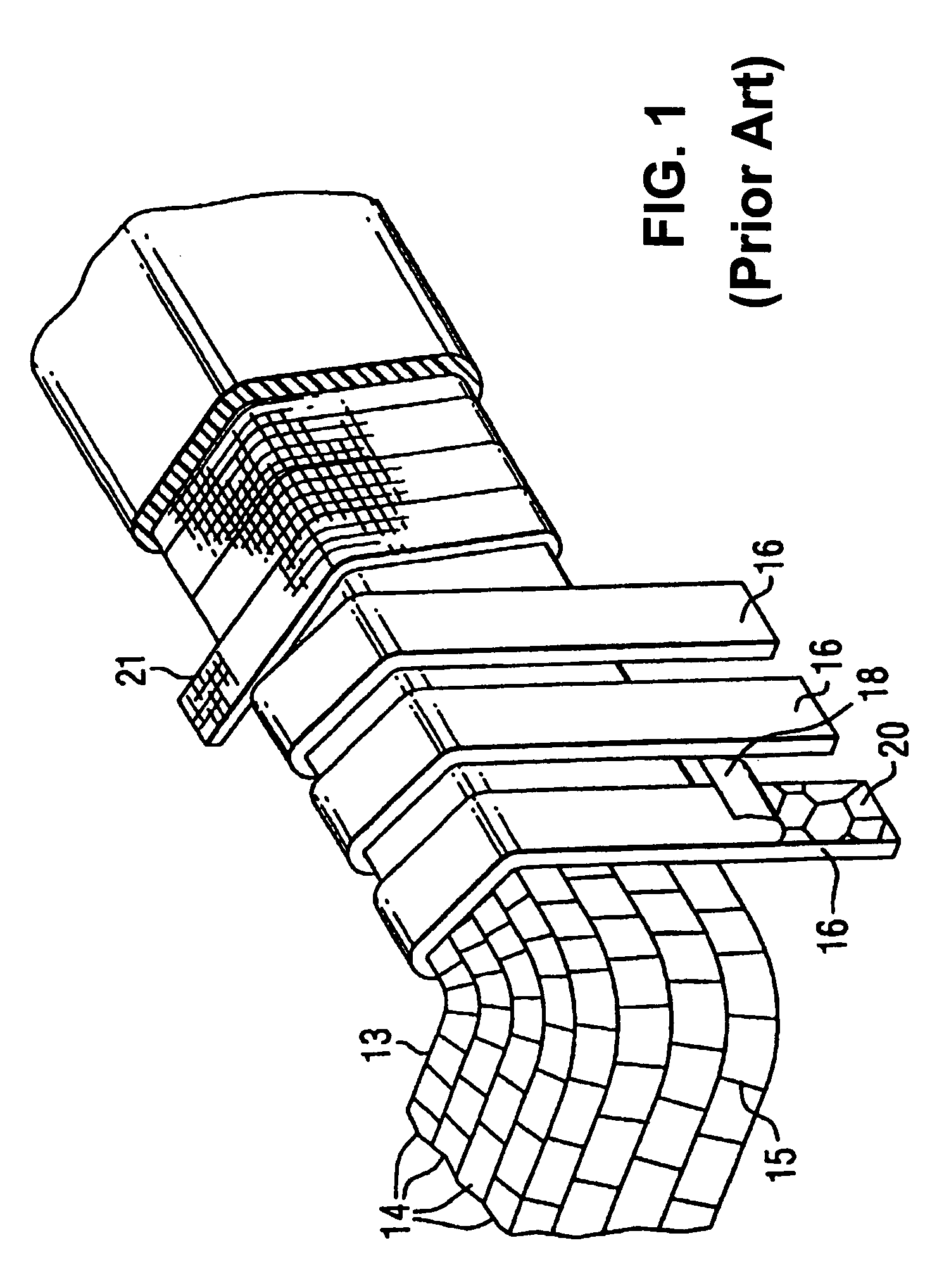
[0010]High Thermal Conductivity (HTC) organic-inorganic hybrid materials may be formed from discrete two-phase organic-inorganic composites, from organic-inorganic continuous phase materials based on molecular alloys and from discrete organic-dendrimer composites in which the organic-inorganic interface is non-discrete within the dendrimer core-shell structure. Continuous phase material structures may be formed which enhance phonon transport and reduce phonon scattering by ensuring the length scales of the structural elements are shorter than or commensurate with the phonon distribution responsible for thermal transport, and / or that the number of phonon scattering centers are reduced such as by enhancing the overall structural order of the matrix, and / or by the effective elimination or reduction of interface phonon scattering within the composite. Continuous organic-inorganic hybrids may be formed by incorporating inorganic, organic or organic-inorganic hybrid nano-particles in linear or cross-linked polymers (including thermoplastics) and thermosetting resins in which nano-particles dimensions are of the order of or less than the polymer or network segmental length (typically 1 to 50 nm or greater). These various types of nano-particles will contain reactive surfaces to form intimate covalently bonded hybrid organic-inorganic homogeneous materials. Similar requirements exist for inorganic-organic dendrimers which may be reacted together or with matrix polymers or reactive resins to form a continuous material. In the case of both discrete and non-discrete organic-inorganic hybrids it is possible to use sol-gel chemistry to form a continuous molecular alloy. The resulting materials will exhibit higher thermal conductivity than conventional electrically insulating materials and may be used as bonding resins in conventional mica-glass tape constructions, when utilized as unreacted vacuum-pressure impregnation resins and as stand alone materials to fulfill electrical insulation applications in rotating and static electrical power plant and in both high (approximately over 5 kV) and low voltage (approximately under 5 kV) electrical equipment, components and products.

Problems solved by technology

Most inorganic materials do not allow independent selection of structural characteristics such as shape and size and properties to suit different electrical insulation applications or to achieve composites having the right balance of properties and performance.

Method used


Image

  • Nano and meso shell-core control of physical properties and performance of electrically insulating composites
  • Nano and meso shell-core control of physical properties and performance of electrically insulating composites
  • Nano and meso shell-core control of physical properties and performance of electrically insulating composites

Examples


Embodiment Construction

[0028]The present invention provides for a high thermal conductivity (HTC) composite. HTC composites comprise a resinous host network combined with nano, meso and micro fillers that are two phase organic-inorganic hybrid materials. The organic-inorganic hybrid materials are formed from two phase organic-inorganic composites, from organic-inorganic continuous phase materials that are based on molecular alloys, and from discrete organic-dendrimer composites in which the organic-inorganic interface is non-discrete with the dendrimer core-shell structure. Phonon transport is enhanced and phonon scattering is reduced by not only the distribution of the HTC fillers, but also the ordered resin shell (ORS) created around the HTC fillers. In particular, various embodiments can be used to form overlapping ordered resin shells.

[0029]Engineered electrically conducting and insulating composite materials having prescribed physical properties and performance characteristics may be formulated with ...


PUM

PropertyMeasurementUnit
lengthaaaaaaaaaa
diameteraaaaaaaaaa
path lengthaaaaaaaaaa

Abstract

A high thermal conductivity resin that is made up of a host resin matrix (42) and high thermal conductivity fillers (30) that are mixed within the host resin to form a resin mixture. The fillers comprise at least 3-5% by weight of the resin mixture, and the fillers are from an average of 1-100 nm in at least one dimension, and where the particles are smaller than an average of 1000 nm in the particles' longest dimension. The host resin matrix forms an ordered resin shell (40) around the high thermal conductivity fillers (30), whereby resin molecules are aligned perpendicular to the surface of the high thermal conductivity fillers. An overlap of the ordered resin shells (44) is formed between the high thermal conductivity fillers such that continuous pathways for ordered resin shells are created through the resin mixture.

Description

CROSS-REFERENCE TO RELATED APPLICATIONS[0001]This application is a continuation-in-part of U.S. application Ser. No. 11 / 152,983, “High Thermal Conductivity Materials Incorporated into Resins” filed Jun. 14, 2005 now abandoned, by Smith, et al., which is incorporated herein by reference.FIELD OF THE INVENTION[0002]The field of the invention relates to the fillers within a host resin matrix and their interaction therewith.BACKGROUND[0003]With the use of any form of electrical appliance, there is a need to electrically insulate conductors. With the push to continuously reduce the size and to streamline all electrical and electronic systems there is a corresponding need to find better and more compact insulators and insulation systems.[0004]Various epoxy resin materials have been used extensively in electrical insulation systems due to their practical benefit of being tough and flexible electrical insulation materials that can be easily adhered to surfaces. Traditional electrical insula...

Claims


Application Information

Patent Timeline
Patent Type & Authority Patents(United States)
IPC IPC(8): B32B5/16B32B27/38B32B29/00
CPCH05K1/0373H05K2201/0209H05K2201/0224H05K2201/0248Y10T428/258Y10T428/256Y10T428/251Y10T428/257Y10T428/254Y10T428/25Y10T428/259Y10T428/31511Y10T428/31993C08K3/14C08K3/22C08K9/08H05K1/03
Inventor STEVENS, GARYSMITH, JAMES D. B.WOOD, JOHN W.
Owner SIEMENS ENERGY INC
Learn More