Tuning fork flexural crystal vibration device, crystal vibrator, and crystal oscillator

a vibration device and flexural crystal technology, applied in the direction of oscillation generators, generators/motors, instruments, etc., can solve the problems of low productivity, difficult to form grooves with the bottom surfaces,

Active Publication Date: 2010-12-14
KYOCERA CORP
View PDF4 Cites 13 Cited by
  • Summary
  • Abstract
  • Description
  • Claims
  • Application Information

AI Technical Summary

Benefits of technology

[0014]It is an object of the present invention to provide a tuning fork flexural crystal vibration device which makes the peak temperature of a temperature characteristic coincide with a reference temperature while suppressing a CI value to a conventional value or less, and a crystal vibrator or crystal oscillator which incorporates the tuning fork flexural crystal vibration device.

Problems solved by technology

In a tuning fork flexural crystal vibration device in which grooves are formed in the front and rear main surfaces of each vibration arm with the bottom surfaces of the two grooves facing each other, it is not easy to form grooves with the bottom surfaces of the two grooves accurately facing each other.
This formation process requires complicated manufacturing steps, and hence may lead to low productivity.

Method used


Image

  • Tuning fork flexural crystal vibration device, crystal vibrator, and crystal oscillator
  • Tuning fork flexural crystal vibration device, crystal vibrator, and crystal oscillator
  • Tuning fork flexural crystal vibration device, crystal vibrator, and crystal oscillator

Examples


first embodiment

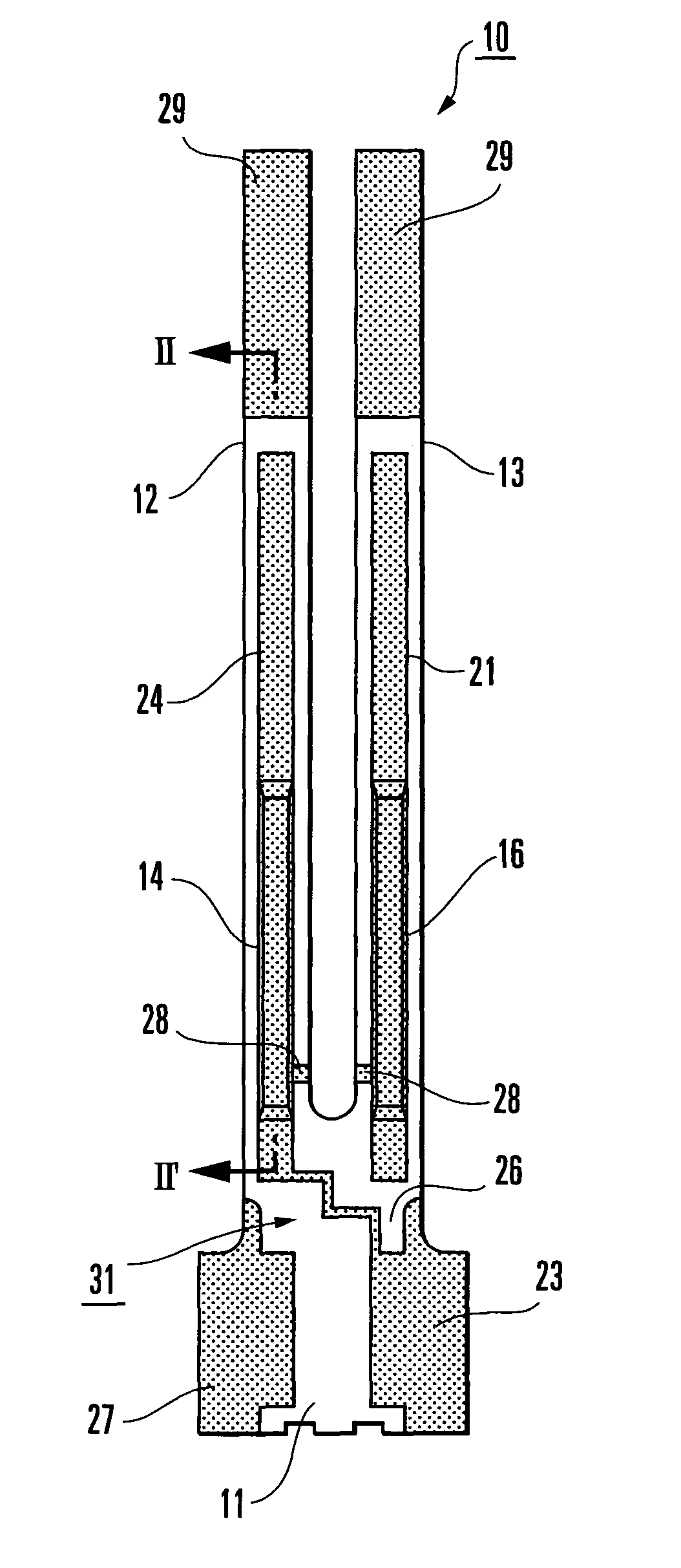
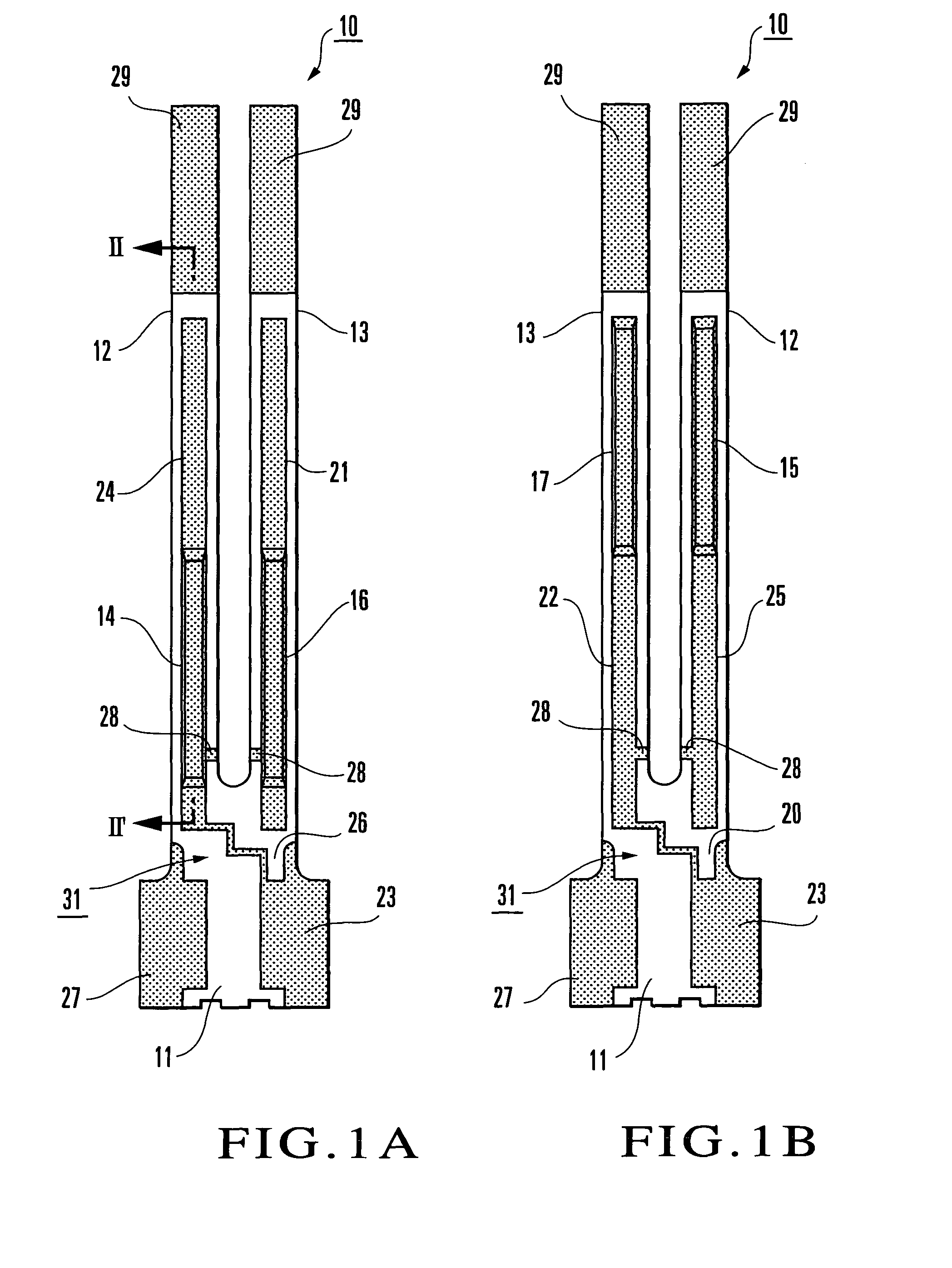
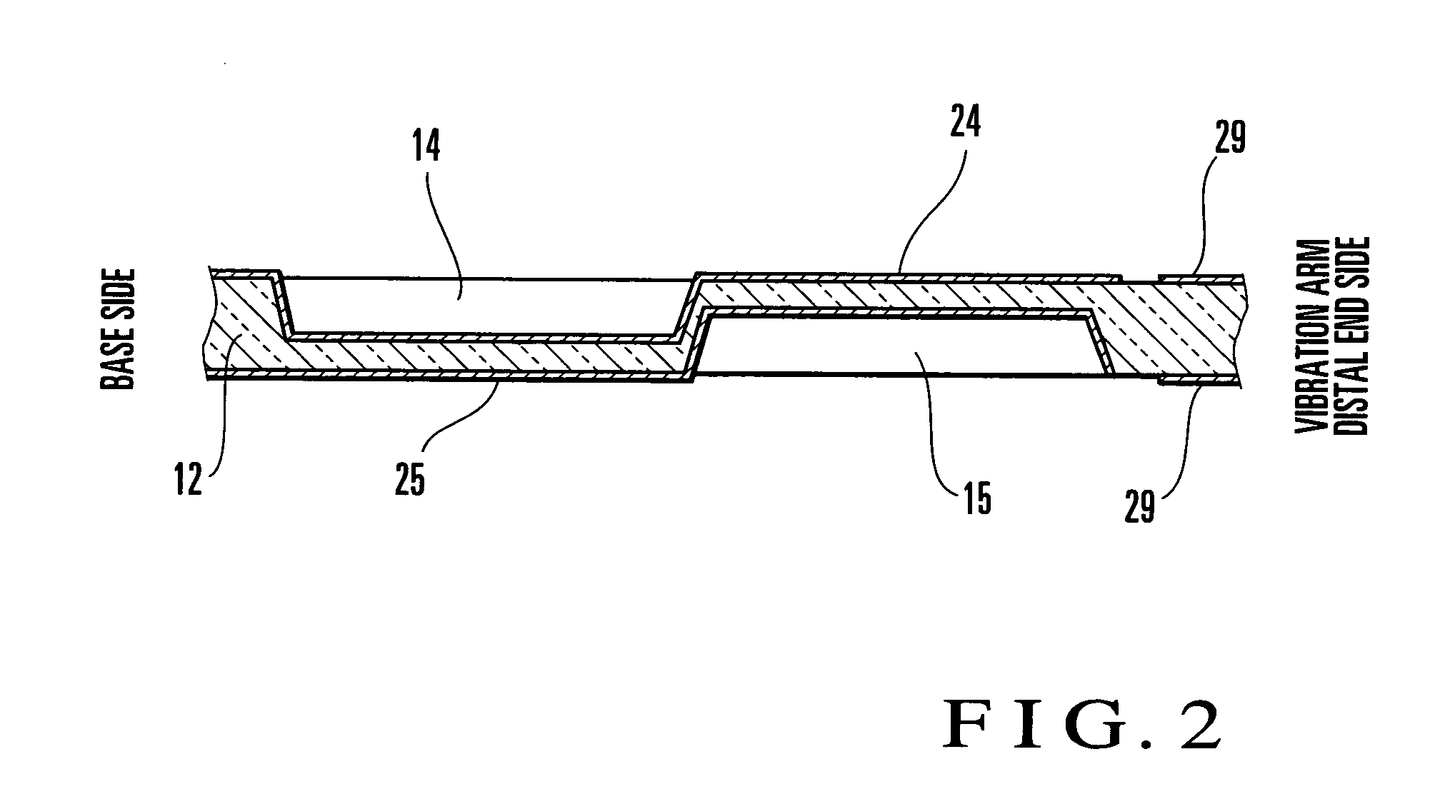
[0032]An example of a tuning fork flexural crystal vibration device according to the first embodiment of the present invention will be described with reference to FIGS. 1A, 1B to 3A, and 3B. As shown in FIGS. 1A and 1B, a tuning fork flexural crystal vibration device 10 according to the first embodiment of the present invention is obtained by forming electrodes and wirings (to be described later) on the surface of a crystal piece 31 like that shown in FIGS. 3A and 3B, which is made of a crystal material having a tuning fork-like outer shape.

[0033]The crystallographic axis direction of the crystal piece 31 of the tuning fork flexural crystal vibration device 10 is defined such that the widthwise direction, longitudinal direction, and thickness direction of the crystal piece 31 are set to the X-axis direction, Y′-axis direction, and Z′-axis direction, respectively. The crystal piece 31 comprises a base 11 having an almost rectangular flat plate shape when viewed from the top and first...

second embodiment

[0043]An example of a tuning fork flexural crystal vibration device according to the second embodiment of the present invention will be described next with reference to FIGS. 4A and 4B. As shown in FIGS. 4A and 4B, a crystal piece 41 of the tuning fork flexural crystal vibration device according to the second embodiment of the present invention mainly comprises a base 11, a first vibration arm 12, and a second vibration arm 13. The crystal piece 41 has almost the same shape as that of the crystal piece 31 according to the first embodiment shown in FIGS. 3A and 3B. Note however that each groove is formed in the crystal piece 41 in FIGS. 4A and 4B in the following manner. For example, compared with the first groove 14 shown in FIG. 3A, two grooves 14a and 14b are divisionally formed in the longitudinal direction of the first vibration arm 12 so as to have openings in the front and rear main surfaces of the first vibration arm 12, respectively.

[0044]Likewise, compared with the second g...

third embodiment

[0048]An example of a tuning fork flexural crystal vibration device according to the third embodiment of the present invention will be described next with reference to FIGS. 5A and 5B. As shown in FIGS. 5A and 5B, a crystal piece 51 of the tuning fork flexural crystal vibration device according to the third embodiment of the present invention mainly comprises a base 11, a first vibration arm 12, and a second vibration arm 13. The crystal piece 51 has almost the same shape as that of the crystal piece 31 according to the first embodiment shown in FIGS. 3A and 3B. Note however that each groove is formed in the crystal piece 51 in FIGS. 5A and 5B in the following manner. For example, compared with the first groove 14 shown in FIG. 3A, two grooves 14c and 14d are divisionally formed in the widthwise direction of the first vibration arm 12 so as to have openings in the front main surface of the first vibration arm 12. That is, the grooves 14c and 14d are arranged parallel to the widthwis...


PUM


Abstract

A tuning fork flexural crystal vibration device includes a base, two vibration arms, grooves, electrodes, and wirings. The base has a flat plate shape. The two vibration arms have flat panel shapes extending from a side surface of the base in the same direction. The grooves are provided for the two vibration arms so as to extend from base-side end portions of the vibration arms along the longitudinal direction of the vibration arms and are depressed in the thickness direction of the vibration arms. The grooves include front-side grooves which open in the front main surfaces of the vibration arms and are provided at least one by one for each vibration arm, and rear-side grooves which open in the rear main surfaces of the vibration arms and are provided at least one by one for each vibration arm. The bottom surface of the front-side groove does not face the bottom surface of the rear-side groove provided in the same vibration arm in which the front-side groove is provided. The electrodes are formed on the surfaces of the base and the two vibration arms. The wirings electrically connect the electrodes to each other. A crystal vibrator and crystal oscillator are also disclosed.

Description

BACKGROUND OF THE INVENTION[0001]The present invention relates to a tuning fork flexural crystal vibration device, a crystal vibrator incorporating the crystal vibration device, and a crystal oscillator incorporating the crystal vibration device or the crystal vibrator.[0002]A crystal vibrator or crystal oscillator incorporating a tuning fork flexural crystal vibration device as one of electronic components is mounted and used as a reference signal source or clock signal source in an electronic device such as a computer, a cellular phone, or a compact information device. Strong demands for downsizing, lower profile, and cost reduction have been conventionally imposed on the crystal vibrator and crystal oscillator. A conventional tuning fork flexural crystal vibration device will be described below with reference to the accompanying drawings.[0003]Referring to FIGS. 9A, 9B, and 10, in a tuning fork flexural crystal vibration device 100, various types of electrodes, e.g., vibration el...

Claims


Application Information

Patent Timeline
Patent Type & Authority Patents(United States)
IPC IPC(8): H01L41/08H01L41/053
CPCG01C19/5607H03B5/30H03H9/1021H03H9/21
Inventor KIZAKI, SHIGERU
Owner KYOCERA CORP
Why Eureka
Try Eureka