Air gun vibration damper and method

a technology of vibration damper and air gun, which is applied in the field of air guns, can solve the problems and achieve the effect of damping the vibration of the power spring

Inactive Publication Date: 2010-12-21
GORE THOMAS D
View PDF9 Cites 21 Cited by
  • Summary
  • Abstract
  • Description
  • Claims
  • Application Information

AI Technical Summary

Benefits of technology

[0005]Vibrations exhibited by typical power spring air guns are damped by providing a damping component operatively connected to the power spring and configured to damp vibrations in the air gun when the air gun is fired. The damping component may have at least a portion that is annular, such as a sleeve or sleeve portion, concentrically surrounding at least a portion of the power spring and configured to contact the compression piston and the power spring. The damping component may be a layer of damping material on the tubular body that moves with the body free from contact with an air gun compression piston and a power spring piston. This layer damps the vibration in the power spring both during and after firing. The damping component may be a counterweight concentrically mounted with respect to the power spring and configured to counter recoil in the air gun after firing of the air gun.
[0008]One advantage of the damper provided is that the damping component improves projectile velocities and accuracies by damping the vibrations caused by the power spring it is mounted to.
[0010]Still another advantage of some embodiments of the damper is a layer that covers substantially the entire diametral surface of a tubular gas spring body, and provides a large surface area to abut and absorb vibrations from the power spring.
[0011]Yet another advantage of the damper is that in one embodiment, the inside mounted layer includes a narrow neck at the forward end of the power spring. This neck frictionally grips the retaining head of the spring's piston to prevent the piston from bouncing back from the post-firing position.
[0012]Still yet another advantage of an inside mounted layer embodiment having a narrowed neck is that the neck's abutting relationship to the piston when it is in a post-firing position transfers any vibrations in the piston to the vibration damping layer.
[0014]Still a further advantage is that in some embodiments a counter-weight is mounted the the spring body. The counter-weight may be sized to fit within a skirted piston and is slidable within the piston such that when the air gun is fired and the skirted piston comes to an abrupt stop, the counter-weight will slide and strike a portion of the air gun to counter the recoil effect of firing.

Problems solved by technology

This layer damps the vibration in the power spring both during and after firing.

Method used


Image

  • Air gun vibration damper and method
  • Air gun vibration damper and method
  • Air gun vibration damper and method

Examples


Embodiment Construction

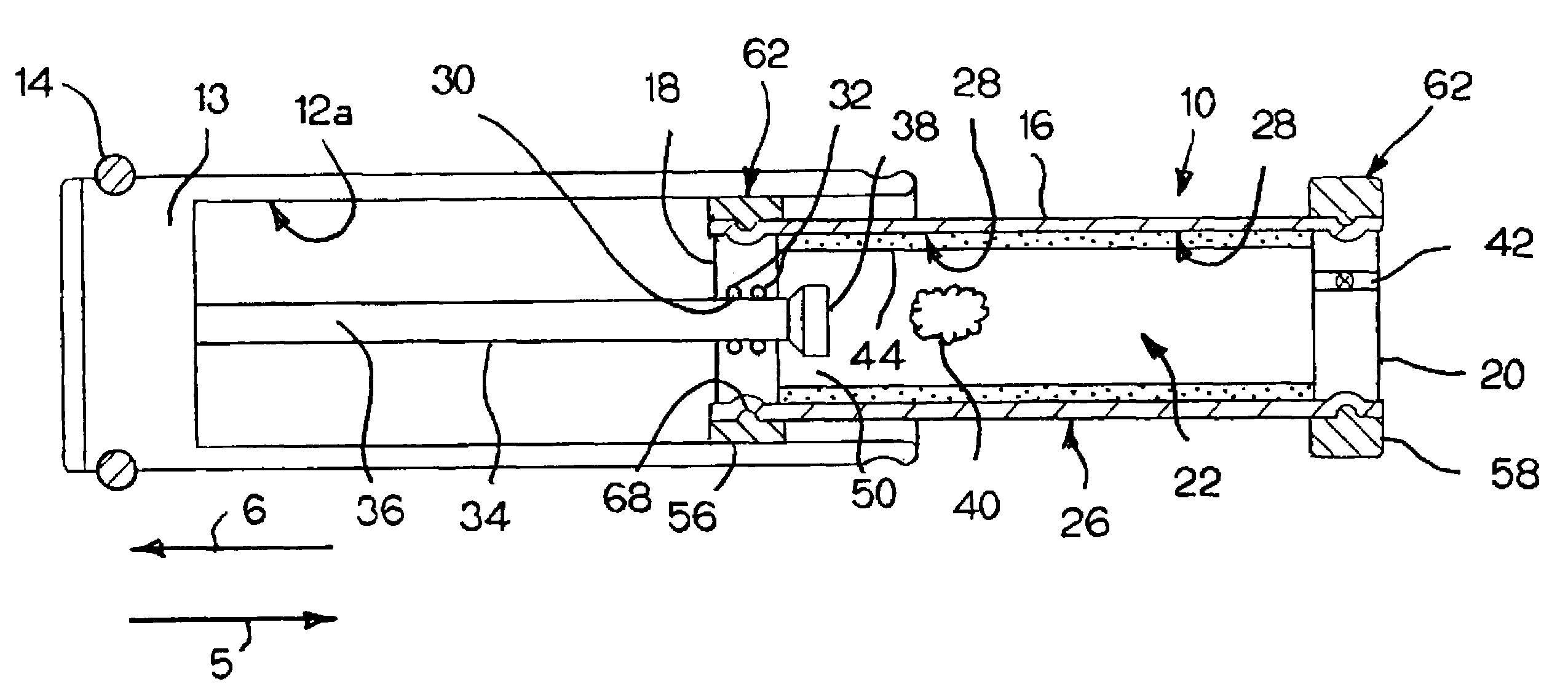
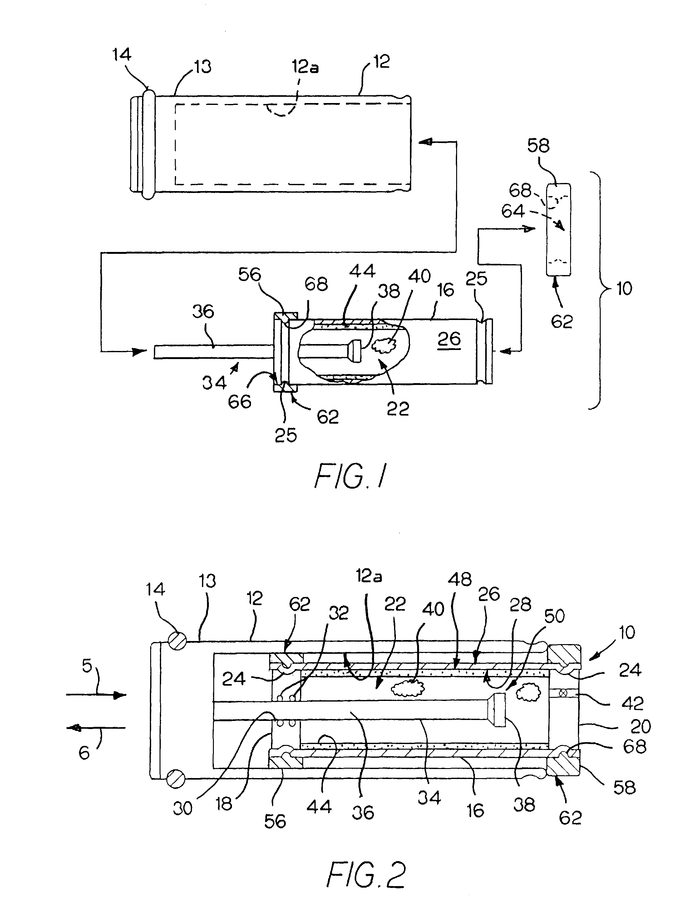
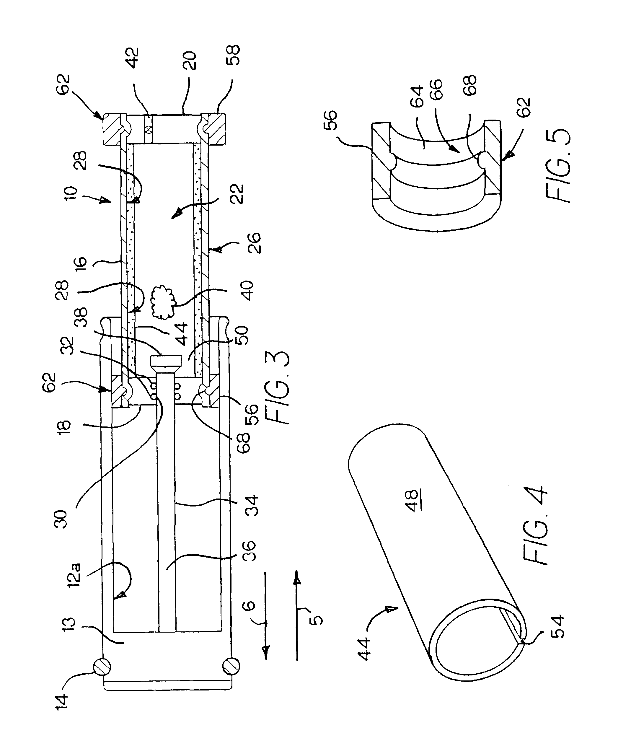
[0029]Referring now to FIGS. 1-3, a gas spring 10 is shown along with a tubular shaped or skirted compression piston 12 for an air-powered pellet gun. The compression piston 12 is conventional and has a front end or head 13 having a dynamic seal or gasket 14 which creates an air-tight seal between compression piston 12 and the inner surface of the air gun's compression tube (not shown). In a typical air gun, the compression tube and compression piston 12 are substantially in-line with the air gun's barrel (not shown), such that once the air gun's trigger is pulled, the compression piston 12 moves toward the barrel and compresses the air in the compression tube in front of the piston head 13 expelling a projection, e.g., a pellet, out of the barrel.

[0030]Gas spring 10 includes an elongated tubular body 16. A pair of end walls or plugs 18, 20 are fixed to body 16 to define a pressure chamber 22. In the embodiment shown, plugs 18, 20 are fixed within the chamber 22 by roll forming annu...


PUM


Abstract

A gas spring having an internal vibration damper for an air gun charging system. The gas spring including a relatively thin liner which is received within and abuts the elongated inner and / or outer wall of the tubular gas spring. The liner(s) absorbs vibration in the air gun to improve firing performance. A guide sleeve mounted to the outer surface of the gas spring abuts an air gun's tubular compression piston to transfer any vibrations in the compression piston to the liner. A tubular counter-weight is slidably mounted about the outer wall of the gas spring and strikes a forward end of the charging system after the air gun is fired to counter the post-firing recoil.

Description

FIELD OF THE INVENTION[0001]This invention relates to air guns and more particularly to a vibration damper for the force producing / charging assembly of a gas spring air gun.BACKGROUND OF THE INVENTION[0002]Air guns use compressed air to discharge a pellet. Some air guns use a firing piston in a compression chamber. In a gas spring-type air gun, the air gun is charged by moving this compression piston toward the trigger to compress a gas contained within a gas spring's cylinder behind the compression piston.[0003]The gas spring is mounted between the compression piston and a trigger mechanism. The compression piston is retracted to cock the trigger and to compress the gas contained within the gas spring. The gas within the gas spring is compressed by a second piston, hereinafter, the spring piston. When the trigger is released, the gas spring launches the compression piston toward the barrel to compress the air in the compression chamber. The compressed air then propels the pellet th...

Claims


Application Information

Patent Timeline
Patent Type & Authority Patents(United States)
IPC IPC(8): F41B11/00
CPCF41B11/642F41C27/22
Inventor GORE, THOMAS D.
Owner GORE THOMAS D
Why Eureka
Try Eureka