Cooling system for electronic equipment

a technology of electronic equipment and cooling system, which is applied in the direction of domestic cooling apparatus, electric apparatus casing/cabinet/drawer, instruments, etc., can solve problems such as system stoppage, and achieve the effects of efficient cooling, low running cost, and precise operation

Inactive Publication Date: 2010-12-21
HITACHI LTD
View PDF32 Cites 67 Cited by
  • Summary
  • Abstract
  • Description
  • Claims
  • Application Information

AI Technical Summary

Benefits of technology

[0008]Incidentally, in the conventional cooling system for an electronic device, electronic devices are cooled by not only cooling by an air-conditioning machine, but also by using a cooling devices directly attached to the electronic devices in combination, and thereby, the effect of reducing the air-conditioning power of the air-conditioning machine can be expected.

Problems solved by technology

Therefore, when the electronic devices are placed in a high-temperature state, they cause troubles such as system stops.

Method used


Image

  • Cooling system for electronic equipment
  • Cooling system for electronic equipment
  • Cooling system for electronic equipment

Examples


first embodiment

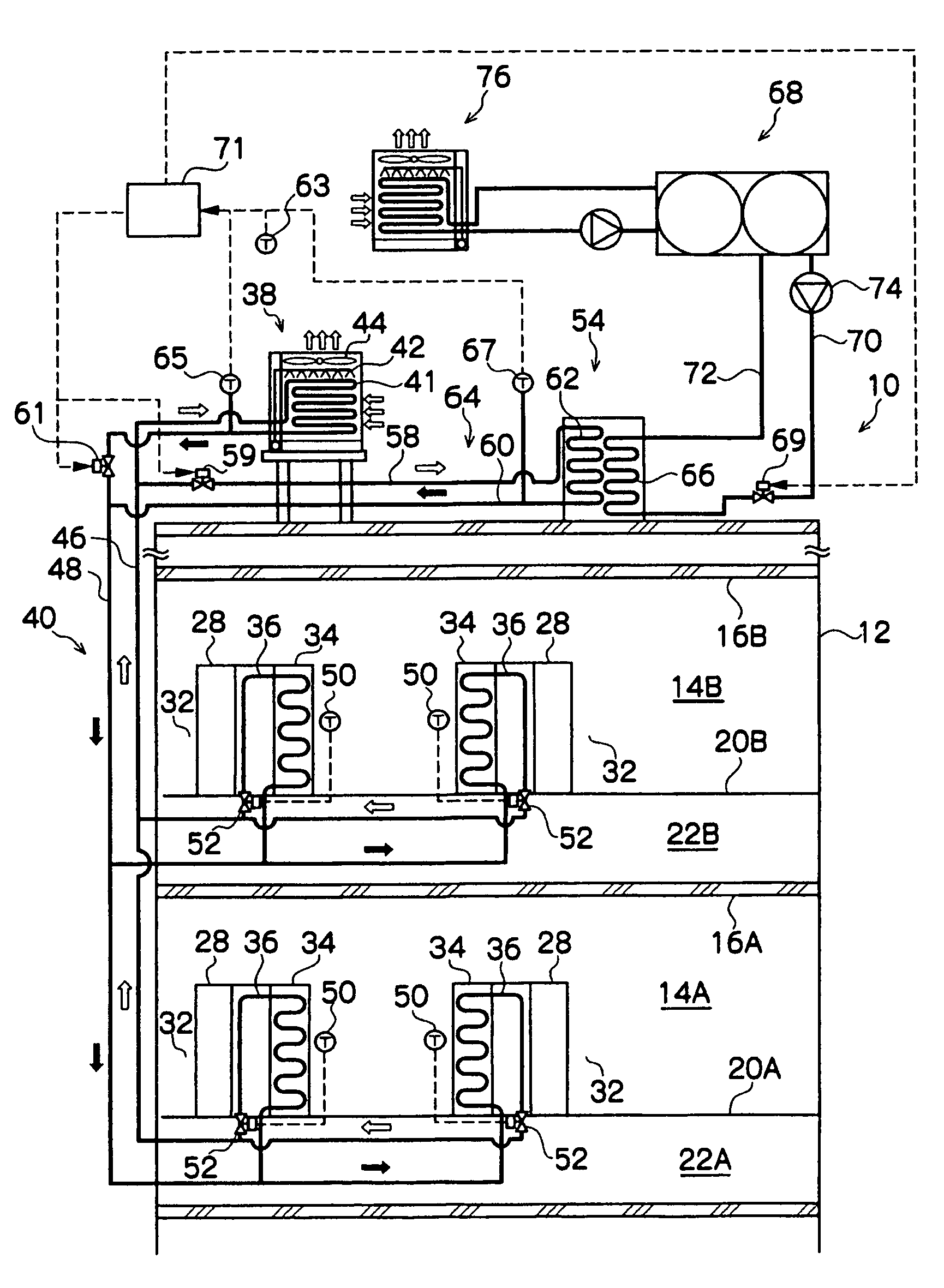
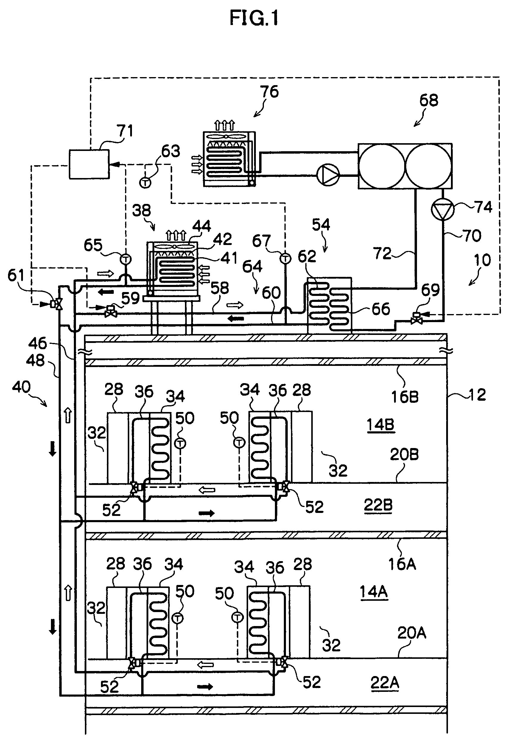
[0054]FIG. 1 is a conceptual view showing a cooling system 10 for an electronic device of a first embodiment of the present invention.

[0055]As shown in FIG. 1, in a two-storied building 12, server rooms 14A and 14B are formed in a first floor and a second floor respectively. Underfloor chambers 22A and 22B are respectively formed on the back sides of floor surfaces 20A and 20B on the first floor and the second floor. A plurality of air outlet ports (not illustrated) are disposed in the floor surfaces 20A and 20B. Cold air from air-conditioning machines 78 (see FIG. 3) which will be described later is blown into the server rooms 14A and 14B from the floor surfaces 20A and 20B through the underfloor chambers 22A and 22B. The air outlet ports are preferably disposed in the vicinity of the front surface side of each of servers 28, and the cold air blown from them is supplied to the servers 28, whereby the servers 28 can be efficiently cooled.

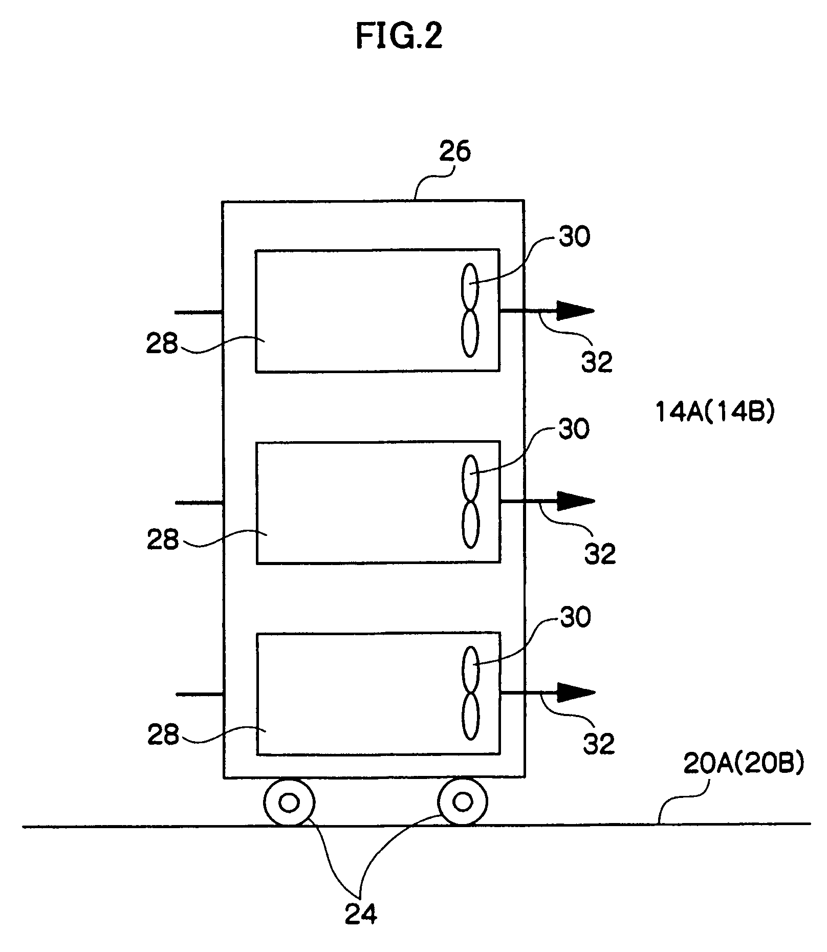
[0056]As shown in FIG. 2, server racks 26 are...

second embodiment

[0074]FIG. 3 is a conceptual view showing a cooling system 100 for an electronic device of a second embodiment of the present invention. The same members and constitutions as those in the first embodiment will be omitted.

[0075]In the cooling system 100 of the second embodiment, an air-conditioning machine 78 for cooling server rooms 14A and 14B is provided in the constitution of the cooling system 10 of the first embodiment, and the refrigerant of the circulation line 40 is used as a cold heat source of the air-conditioning machine 78.

[0076]More specifically, as shown in FIG. 3, machine rooms 80A and 80B are respectively provided adjacently to the server rooms 14A and 14B, and the air-conditioning machines 78 are installed in the machine rooms 80A and 80B, respectively. Further, inlet ducts 79 which take the air of the server rooms 14A and 14B into the air-conditioning machine 78 via the machine rooms 80A and 80B are placed by being penetrated through partition walls 82 which partit...

third embodiment

[0081]FIG. 4 is a conceptual view showing a cooling system 200 for an electric device of a third embodiment of the present invention. Explanation of the same members and constitutions as those in the second embodiment will be omitted.

[0082]The cooling system 200 of the third embodiment has the constitution in which a plurality of servers 28 equipped with the evaporators 34 are divided into groups, and thereby, the cooling system 200 can be operated with the groups being edge-cut from each other, in addition to the constitution of the cooling system 100 of the second embodiment.

[0083]More specifically, as shown in FIG. 4, a plurality of the servers 28 equipped with the evaporators 34 are divided into a plurality of groups. In the case of FIG. 4, the servers 28 installed in the server room 14A on the first floor are grouped as one group, and the servers 28 installed in the server room 14B on the second floor are grouped as another group. The method for grouping is not limited to the a...


PUM


Abstract

In a cooling system for an electronic device of the present invention, server rooms in which a plurality of servers are placed, an evaporator which is provided close to each of the servers, and cools exhaust air from the server by vaporizing a refrigerant with heat generating from the server, a cooling tower which is provided at a place higher than the evaporator, cools the refrigerant by outside air and water sprinkling, and condenses the vaporized refrigerant, and a circulation line in which the refrigerant naturally circulates between the evaporator and the cooling tower. According to the cooling system, an electronic device which is required to perform a precise operation with a heat generation amount from itself being large, such as a computer and a server, can be efficiently cooled at low running cost.

Description

BACKGROUND OF THE INVENTION[0001]1. Field of the Invention[0002]The present invention relates to a cooling system for an electronic device, and particularly, to a cooling system for an electronic device for efficiently cooling an electronic device which is required to perform a precise operation with a heat generation amount from itself being large, such as a computer and a server.[0003]2. Description of the Related Art[0004]In recent years, with improvement in the information processing technique and development of the Internet environments, the information processing amount which is required has increased, and data processing centers for processing various kinds of information in large volume are in the spotlights as business. For example, in the server room of the data processing center, a number of electronic devices such as computers and servers are installed in the concentrated state, and are continuously operated night and day. Generally, for installation of electronic device...

Claims


Application Information

Patent Timeline
Patent Type & Authority Patents(United States)
IPC IPC(8): H05K7/20
CPCF25B25/00H05K7/20827F25B6/02F25B2339/041F25B2700/2106F25B2700/21173F28D5/02F28D15/00
Inventor KASHIRAJIMA, YASUHIROKIKUCHI, HIROSHIGESUGIURA, TAKUMIWATANABE, KOJINAKASHIMA, KENICHI
Owner HITACHI LTD
Why Eureka
Try Eureka