RF circuit modules and integrated chassis with power interface for RF circuit modules

a technology of rf circuit modules and chassis, which is applied in the direction of support structure mounting, electrical apparatus construction details, power supplies, etc., can solve the problems of limited flexibility and versatility of many prior art modules and chassis systems, and many prior art chassis components are not capable of accepting both active rf modules (amplifiers, rf detector switches, etc.) and passive rf modules (filters, equalizers,

Active Publication Date: 2010-12-21
CANADIAN IMPERIAL BANK OF COMMERCE
View PDF26 Cites 13 Cited by
  • Summary
  • Abstract
  • Description
  • Claims
  • Application Information

AI Technical Summary

Benefits of technology

[0006]Accordingly, it is a principal object of the present invention to provide a versatile and flexible RF management system especially suitable for use in CATV head end environments. The inventive system is characterized by a basic rack-mountable chassis component that can be configured for both front and rear mount applications, for different cable management solutions and for accepting passive, active or a combination of passive and active RF circuit modules.
[0008]Yet another object of the invention is to provide an active RF circuit module such as a power supply or amplifier that is provided with a floating connector for ease in connecting the power supply module or other active module to a power bus connector.
[0011]Another object of the invention is to provide a simple, yet versatile chassis component with an integrated power bus for use with both active and passive RF circuit modules.
[0013]The basic chassis is of simple sheet metal construction designed for vertical mounting of RF circuit modules. The chassis comprises a pair of side walls with flanges for rack mounting. The side walls are connected by upper and lower shallow, U-shaped brackets each provided with slots along one longitudinal edge for receiving mating guide pairs on the tops and bottoms of the RF modules. If the chassis is intended to be used with active RF modules, such as a power supply or amplifier, or with both active and passive RF modules, a planar power bus with 9 connectors is mounted in the upper bracket on the side thereof confronting the lower bracket. A pair of support bars also connects the side walls to strengthen and rigidify the chassis structure.
[0016]The passive modules preferably have cast metal housings with removable front covers and are provided with a cast guide rail on the top and bottom of the housing for mating with the slots in the upper and lower mounting brackets of the chassis. The passive modules are provided with a test point on the front cover for convenient access and may be provided with F, BNC or CamPort® connectors. The removable front cover on the amplifier module allows convenient access to plug-in pads, equalizers and filters in the amplifier circuitry with the module still installed in the chassis.
[0017]The active modules have sheet metal housings also with removable front covers. The active module housings may also be manufactured in a diecast format as well. Handles are mounted on the front covers of the active modules. Test points are also located on the front covers of the active and passive modules and the power supply module has an LED power indicator on the front cover. The power supply module is provided with a 24 VDC output on the rear of the module that facilitates “daisy-chain” powering between chassis in a rack.

Problems solved by technology

The versatility and flexibility of many of these prior art modules and chassis systems are limited by the number and type of modules that can be installed in the chassis, by the cable management components mounted to the chassis and by the connectibility of the various RF modules to each other and to the chassis components.
For instance, many of the prior art chassis components are not capable of accepting both active RF modules (amplifiers, power supplies, RF detector switches), as well as passive RF modules (splitters, combiners, attenuators, equalizers, filters).

Method used


Image

  • RF circuit modules and integrated chassis with power interface for RF circuit modules
  • RF circuit modules and integrated chassis with power interface for RF circuit modules
  • RF circuit modules and integrated chassis with power interface for RF circuit modules

Examples


Embodiment Construction

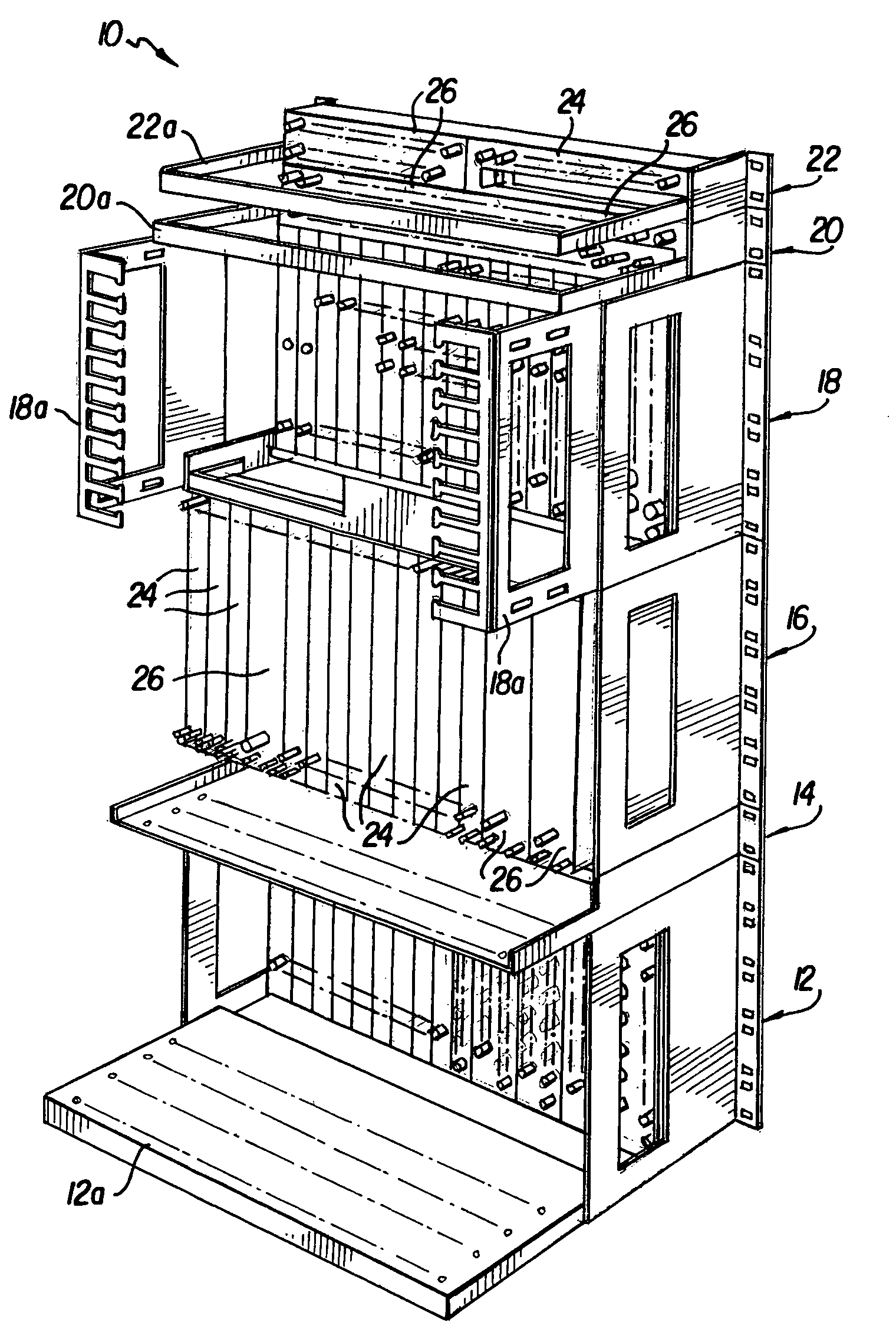
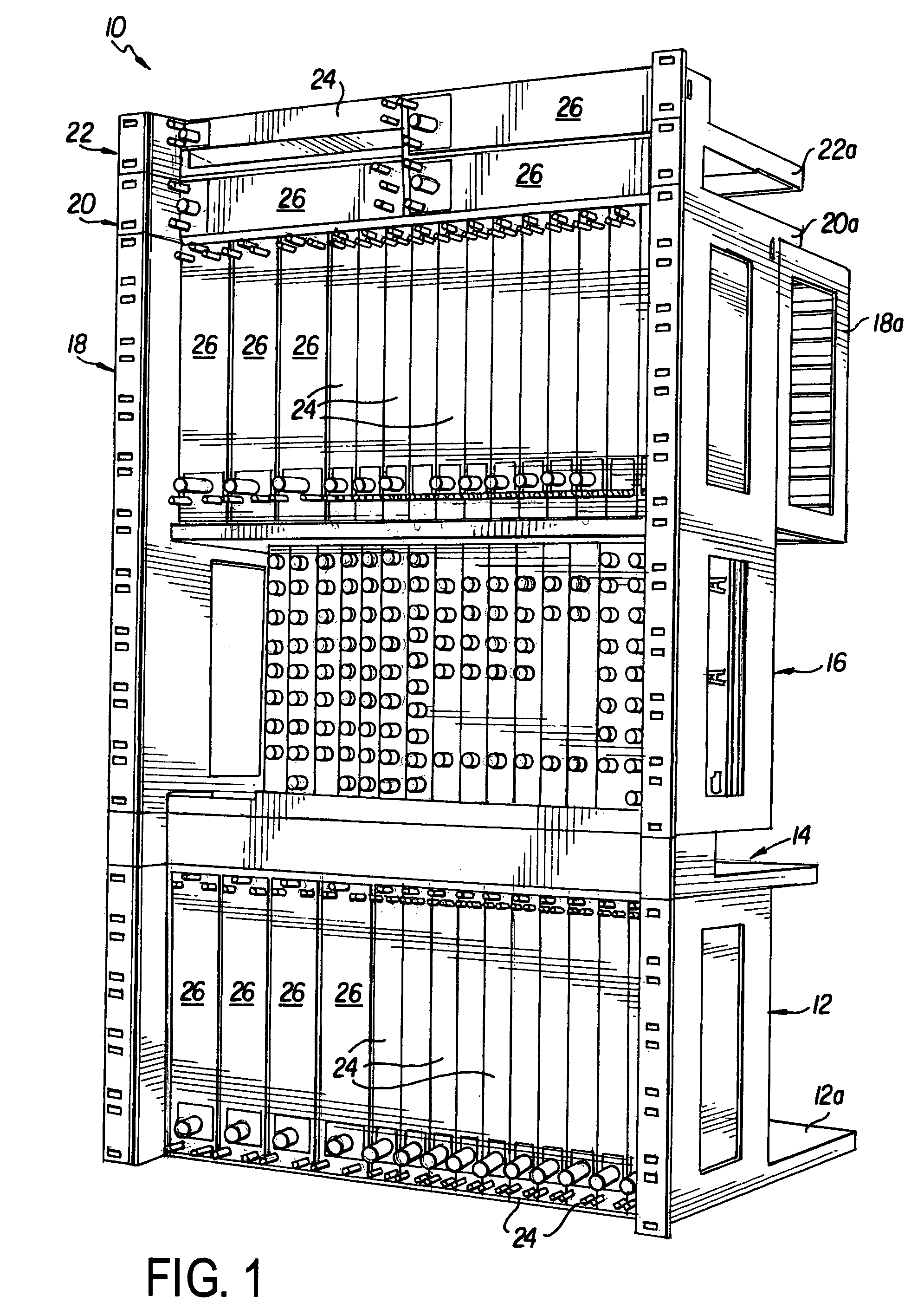
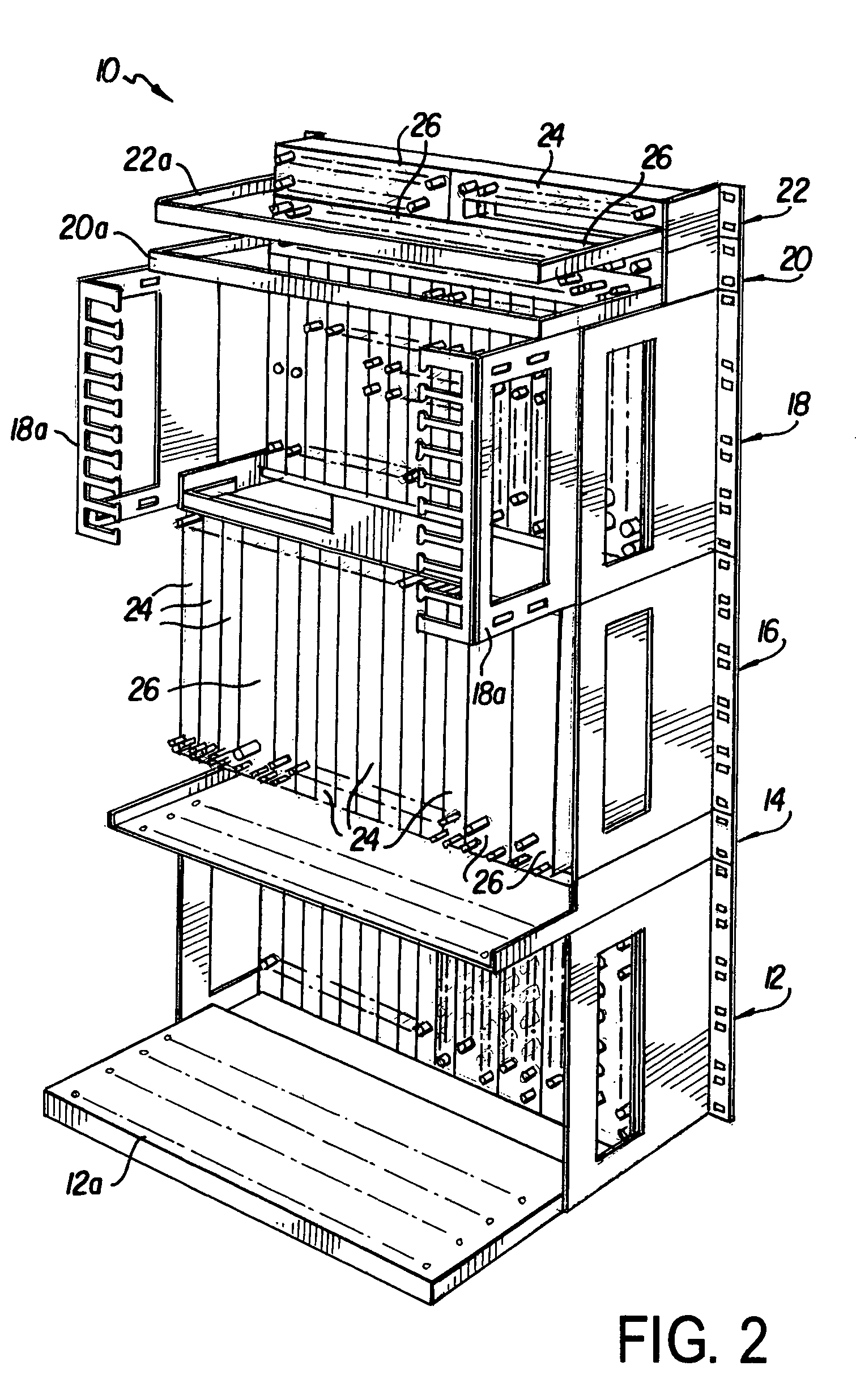
[0036]Referring now to the drawings in detail, FIGS. 1 and 2 illustrate front and rear perspective views of an RF management system comprising a typical arrangement 10 of passive RF circuit modules in a plurality of the rack mountable chassis of the present invention shown without cable connections for clarity. The arrangement 10 includes, from bottom to top, a 5 rack unit passive chassis 12 for vertically front mounted modules with a horizontal cable management tray 12a, a one rack unit slotted cable management tray 14, a 5 rack unit passive chassis 16 for vertically rear mounted modules, a 5 rack unit passive chassis 18 for vertically front mounted modules with cable management ears 18a, and two one rack unit passive chassis 20, 22 for horizontally front mounted modules with cable management bars 20a, 22a. Chassis 12 has eighteen module stations in which ten single station passive modules 24 and four double station passive modules 26 are front mounted. Chassis 16 has eighteen modu...


PUM


Abstract

An RF management system especially suitable for use in CATV head end environments is disclosed. The system is characterized by a basic rack-mountable chassis component that can be configured for both front and rear mount applications, for different cable management solutions and for accepting eighteen passive RF modules or nine active RF modules or a combination of passive and active RF circuit modules. The active configuration of the chassis has an integrated power bus with at least nine connectors for receiving up to nine active RF circuit modules. The active RF circuit modules, such as power supplies and amplifiers are each provided with a “floating” connector for ease in connecting the power supply module or amplifier module to the power bus. The RF power supply module is capable of supplying power to all the active RF modules in the chassis as well as to active RF modules mounted in one or more other chassis in the rack.

Description

[0001]This application is a Division of application Ser. No. 10 / 158,050 Filed on May 31, 2002 now U.S. Pat. No. 6,812,348FIELD OF THE INVENTION[0002]The present invention relates to the field of radio-frequency (RF) management systems and more particularly to modular RF circuit components and chassis configurations for supporting and interconnecting active and passive RF circuit modules.BACKGROUND OF THE INVENTION[0003]In the telecommunications industry, broadband RF signals are delivered to consumers via conductors from a head end located, for example, at the central office of a CATV telecommunications company. At the head end, a variety of RF circuit modules are typically mounted in racks of specially designed chassis components. The RF modules carry out the many kinds of RF signal modifications and manipulations necessary to operate a telecommunications system, such as a CATV system. Many different types of RF circuit modules and chassis for supporting, connecting and managing th...

Claims


Application Information

Patent Timeline
Patent Type & Authority Patents(United States)
IPC IPC(8): H05K7/14H05K9/00
CPCH05K7/1425H05K9/0062
Inventor LEE, JAY
Owner CANADIAN IMPERIAL BANK OF COMMERCE
Why Eureka
Try Eureka