Adjustable pump control linkage for pump driven vehicle

a technology for controlling linkage and pump drive, which is applied in the direction of steering linkage, transportation and packaging, propulsion unit arrangement, etc., can solve the problems of improper setting of linkage assembly length, affecting linkage assembly length, and vehicle may experience a certain amount of unwanted forward or backward creep, so as to shorten or lengthen the effective length of the linkage assembly

Inactive Publication Date: 2010-12-28
SCAG POWER EQUIP +1
View PDF12 Cites 10 Cited by
  • Summary
  • Abstract
  • Description
  • Claims
  • Application Information

AI Technical Summary

Benefits of technology

[0011]In one embodiment, the link includes a rod having a top end and a bottom end. The bottom end is attached to the pump. The top end of the rod is received by an internally threaded insert which is housed in a housing. The internally threaded insert includes an access point for mating with a tool. Upon rotation of the insert using the tool, the insert rotates to drive the rod into or out of the insert and, thereby, vary the effective length of the linkage assembly.
[0015]Another aspect of a preferred embodiment of the present invention includes configuring an internally threaded insert of an embodiment of the assembly so as to be held in a pivoting housing so as to be rotatable relative to the housing. Further, the internally threaded insert is preferably restrained from moving axially with respect to the housing.

Problems solved by technology

For instance, during assembly of the vehicle, the linkage assembly length may be improperly set.
Further, during operation, the linkage assembly may be jostled and otherwise disturbed so as to cause the linkage assembly length to be affected.
As such, the pumps of the vehicle may become uncentered such that, when the lever is positioned in neutral, the vehicle may experience a certain amount of unwanted forward or backward creep.
This adjustment method can be quite difficult in operation because the lower end of the turnbuckle and even the rod can be very difficult to access because they are obstructed by the frame, the seat, and other components of the lawnmower.

Method used


Image

  • Adjustable pump control linkage for pump driven vehicle
  • Adjustable pump control linkage for pump driven vehicle
  • Adjustable pump control linkage for pump driven vehicle

Examples


Embodiment Construction

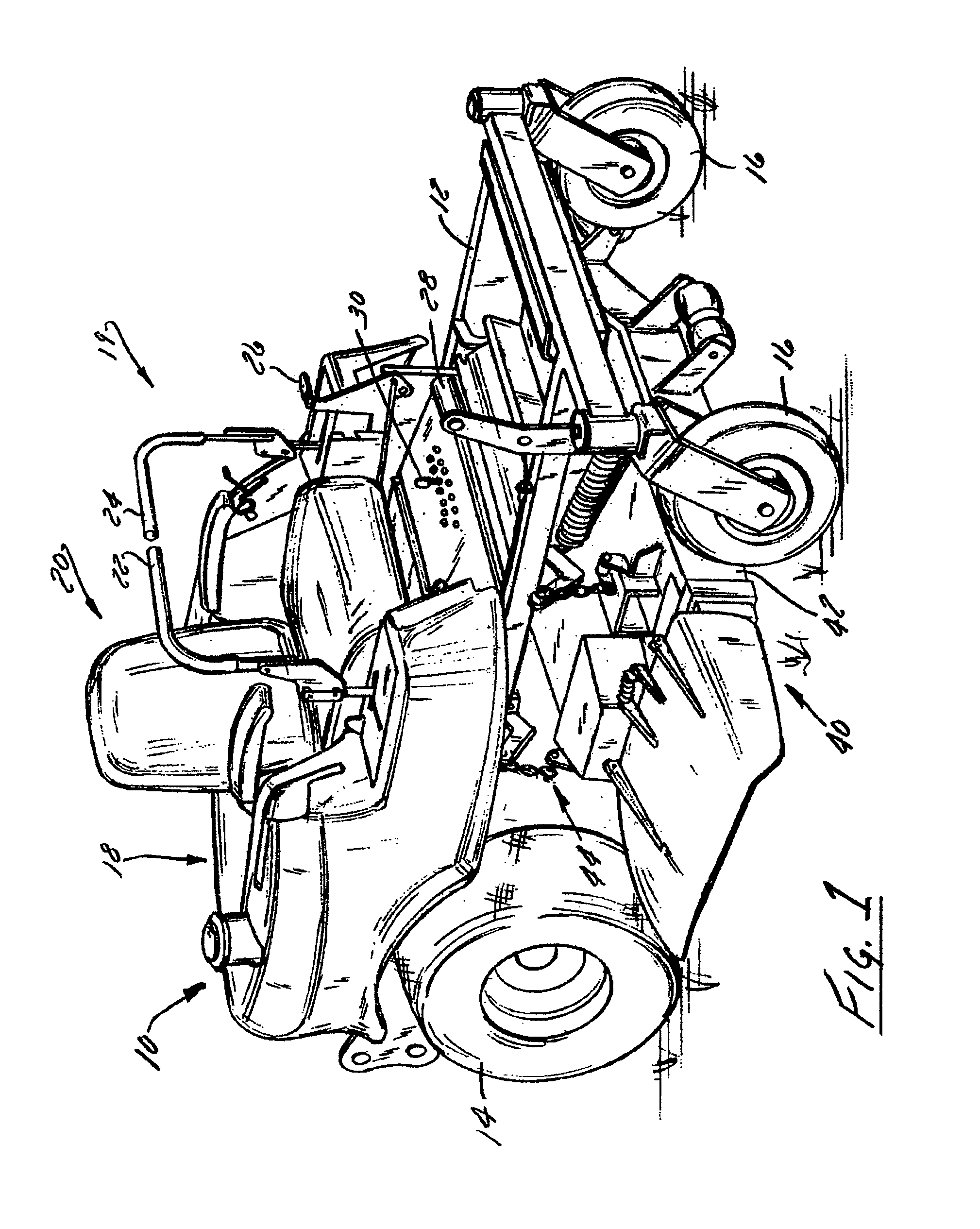
[0033]An adjustable pump control linkage assembly constructed in accordance with a preferred embodiment of the invention is described below in connection with a riding pump-driven vehicle such as a riding lawnmower. It should be understood that the illustrated adjustable pump linkage assembly and others constructed in accordance with the invention could be used with other riding lawnmowers, other walk behind or ride-on lawnmowers, or other pump-driven utility vehicles.

[0034]Referring initially to FIG. 1, a pump powered vehicle in the form of a zero-turn lawnmower 10 includes a frame 12 supported on driven rear wheels 14 and undriven front wheels or casters 16, an engine 18 mounted on the rear of the frame 12, an operator's seat 20 mounted on the frame 12 in front of engine 18, and operator's controls 19. The operator's controls 19 include a steering mechanism for steering the vehicle. The steering mechanism could, for example, be a steering wheel or one or more levers. In the illust...


PUM


Abstract

The effective length of pump control linkage assembly of a pump-driven vehicle such as a zero-turn lawnmower can be adjusted without directly manipulating a rod or similar member forming the major length of the assembly. The length instead can be adjusted from above with a simple tool such as a screwdriver or wrench using a knob or similar device. In one embodiment, the linkage assembly includes a rod having a top end and a bottom end. The bottom end is attached to the pump. The top end of the rod is received by an internally threaded insert which is housed in a housing. The internally threaded insert includes an engagement structure such as a hex head for mating with the tool. Upon rotation of the insert using the tool, the insert rotates to drive the rod into or out of the insert and, thereby, vary the effective length of the linkage assembly.

Description

BACKGROUND OF THE INVENTION[0001]1. Field of the Invention[0002]The invention relates to vehicles powered and steered by pumps. More particularly, the invention relates to an improved pump control linkage assembly for a pump driven vehicle such as a lawnmower.[0003]2. Discussion of the Related Art[0004]Vehicles equipped with hydraulically-powered drive systems that propel the drive wheels of a vehicle are generally known and are common and include, but are not limited to, walk behind lawnmowers, stand-on lawnmowers, and riding lawnmowers. Turning is typically achieved or at least facilitated by driving each drive wheel at different speeds. In some vehicles, they can even be turned in different directions at equal speeds for a very sharp or even a “zero-turn” radius, where the vehicle pivots about the midpoint of drive wheel axis. This kind of drive wheel steering system is more maneuverable than traditional vehicle steering systems that do not vary the relative speed of the drive wh...

Claims


Application Information

Patent Timeline
Patent Type & Authority Patents(United States)
IPC IPC(8): B60K17/14
CPCB60K17/145B60K26/02B60K26/04B60Y2200/223
Inventor SUGDEN, DAVID J.SEITTER, ERIC J.MUGAN, MATTHEW
Owner SCAG POWER EQUIP
Why Eureka
Try Eureka