Dental handgrip

a handgrip and dental technology, applied in dental tools, amalgam presses/mixers, dental tools, etc., can solve the problems of high cost and time-consuming procedure of filling a tooth cavity, large space occupation, and inability to concentrate solely on the user, so as to improve the quality of filling compound, reduce the viscosity of filling compound, and improve the effect of preparation si

Inactive Publication Date: 2010-12-28
W&H DENTALWERK
View PDF17 Cites 9 Cited by
  • Summary
  • Abstract
  • Description
  • Claims
  • Application Information

AI Technical Summary

Benefits of technology

[0013]In another preferred example of embodiment, the handgrip comprises a first end, at which the connection device for the filling compound container is provided and at which one or more light emission areas of the light emission device can be or are also disposed. To advantage, therefore, the use of the handgrip is additionally facilitated for the dentist. The light emission device can either be provided fixed in the region of the first end, or it can also be arranged so as to be mobile, for example displaceable in the handgrip, so that it can be moved if need be in the direction of the first end or up to the first end or beyond it.
[0014]In order to prevent the user from inadvertently delivering filling compound from the filling compound container and directing the light emission device onto the filling compound at the same time, so that for example an undesired, at least partial hardening of the filling compound takes place before the latter has been introduced in the optimum manner into the tooth cavity, the handgrip is provided with a safety device or means to prevent a premature or inadvertent light emission onto the filling compound. These safety means can have the most diverse embodiments, whereby a dental handgrip could have one or more of these safety means. The aim of these safety means is to prevent light from striking the filling compound before the user intends to harden the filling compound, or at least to ensure that the radiant energy or intensity of the light striking the filling compound is so small that a premature hardening reaction caused by the light emission device and disadvantageous to the patient does not take place before the actual hardening is intentionally started by the dentist.
[0015]In a first exemplary embodiment, the safety means comprise the light emission area(s) of the light emission device and the delivery opening(s) of the filling compound container, the light emission area(s) and the delivery opening(s) being disposed in such a way that they point in different directions. Alternatively, or additionally, a device, in particular a mechanical device, for example a rotatable or swivelling cover device, can be provided, which is designed in such a way that either only the light emission area(s) or the delivery opening(s) is / are free, so that only light or filling compound can be delivered, whereas the other of the two elements (light emission area or delivery opening) is covered. Instead of the covering of the light emission area, the device can also be designed such that at least the major part of the light emitted by the light emission device is deflected, shielded or absorbed. The essential point is that the means are designed in such a way that no light can arrive at the filling compound as long as this is not desired by the user, or that only so little light strikes the filling compound that it does not lead to a premature, undesired hardening reaction.
[0018]According to a second aspect, a dental handgrip for the delivery of filling compound with a fluid-operated delivery device for delivering the filling compound from the filling compound container is disclosed, the supply for the handgrip with the driving fluid preferably taking place via an external fluid source. A compressed gas, in particular compressed air, or a liquid, in particular water, can be used as the driving fluid. A coupling element for connecting the delivery device to an external fluid source is preferably also provided on the handgrip, the coupling element particularly preferably being designed in such a way that it can be coupled to a counter-coupling element, which is provided for the connection to a dental hand-held instrument with another function. If the counter-coupling element is part of a dental unit, the quantity of the air fed to the delivery device can be controlled by means of a foot control which is connected to the dental unit. To advantage, the effect of this is that the delivery takes place uniformly and automatically, without the user having to carry out a delivery operation, such as for example operating a lever. All the operating elements for the delivery are not therefore required on the handgrip, so that the user has a better view of the preparation site.
[0019]In another exemplary embodiment, the handgrip comprises a vibration generator, which can be or is connected directly or indirectly to the connection device, so that the vibration generated by the vibration generator can be transmitted to the filling compound, as a result of which the viscosity of the filling compound is reduced and the filling compound can be delivered more easily. The vibration generator is designed as a fluid-operated vibration generator. The vibration generator and the delivery device are preferably connected to one another directly or indirectly, for example via the hollow vibration shaft of the vibration generator, so that at least a part of the fluid can be used for the operation of the delivery device and the vibration generator. A handgrip according to this embodiment is constructed very simply and compactly, especially in terms of production and assembly, as a result of which the production and assembly costs can be significantly reduced. Such a handgrip also uses the driving fluid effectively and sparingly. The connection between the vibration generator and the delivery device can of course also take place via one or more lines, channels, holes or other elements. The connection can also contain other functional elements, such as for example valves, in particular for the pressure control.

Problems solved by technology

The filling of a tooth cavity thus represents a costly and time-intensive procedure for the dentist.
The user is not able to concentrate solely on the precisely targeted introduction of the filling compound into the tooth cavity and the shaping and compaction of the filling compound, but rather must turn part of his attention constantly to the delivery of the filling compound.
The operating elements, especially when they are designed as levers, require a great deal of space and are troublesome when work is carried out in the spacially limited oral cavity, so that various areas of the oral cavity are accessible only with difficulty using such a handgrip.
The operating elements hinder the view of the preparation site.
Finally, a uniform delivery of the filling compound is also not guaranteed.

Method used


Image

  • Dental handgrip
  • Dental handgrip
  • Dental handgrip

Examples


Embodiment Construction

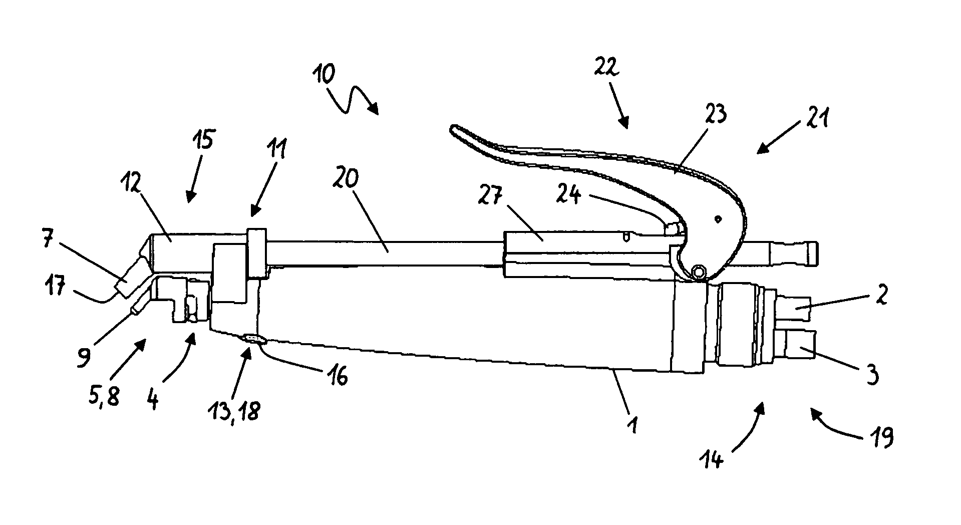
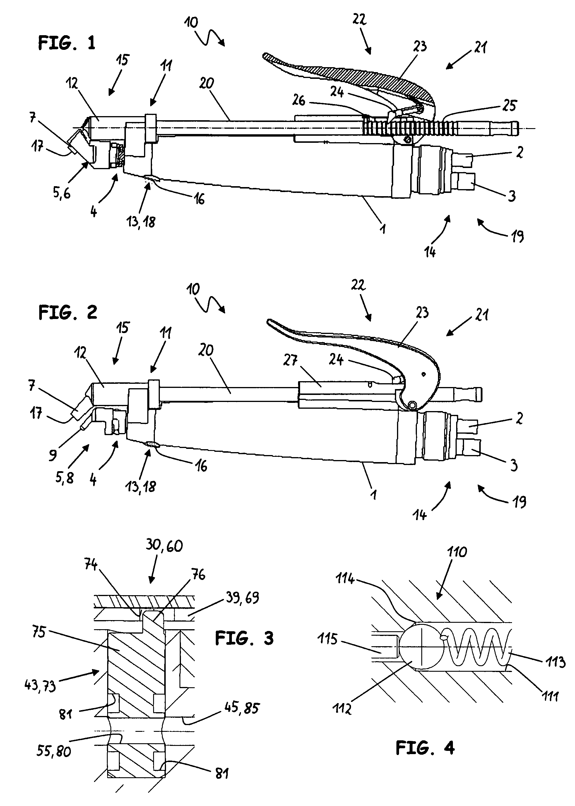
[0042]The dental handgrip 10 represented in FIGS. 1 and 2 for delivering filling compound into a tooth cavity comprises an elongated, essentially cylindrical body with an outer sleeve 1 with a first end 15 and a second end 19. Provided at second end 19 is a coupling element 14, which is preferably designed in such a way that it can be coupled to a counter-coupling element, which is provided for the connection to a dental hand-held instrument with another function. This dental hand-held instrument can in particular be a compressed air-driven turbine handpiece or a tartar removal handpiece. Coupling element 14 comprises at least a first connection 2 to a fluid source, preferably a compressed gas source, in particular to a compressed air source, whereby the fluid can be fed via a line disposed in the interior of handgrip 10 or via channels to a vibration generator (not shown). After passing through the vibration generator, the fluid can be discharged again from handgrip 10 via connecti...


PUM


Abstract

A dental handgrip for delivering filling compound into a tooth cavity is described, the handgrip being provided with a connection device to which a container for the filling compound can be connected. In some embodiments, the handgrip includes a light emission device via which radiation having a wavelength and radiant power for hardening of filling material can be provided. The dental handgrip can include a safety device to prevent a premature or inadvertent light emission onto the filling compound. In some embodiments, the handgrip includes a fluid-operated feeding device for feeding the filling compound from the filling compound container. A vibration generator operable to cause vibrations in the filling compound and to assist in feeding of the compound can also be provided.

Description

CROSS REFERENCE TO RELATED APPLICATION[0001]The present application claims priority from pending European Patent Application No. 06023781.5 and European Patent Application No. 06023782.3, both filed Nov. 16, 2006, which are incorporated herein by reference.BACKGROUND[0002]1. Field[0003]The present application relates to a dental handgrip for delivering filling compound into a tooth cavity.[0004]2. Description of Prior Art[0005]Such a handgrip is known from patent application WO 01 / 17454 A1. It is used for filling hardenable dental compounds comprising plastic compounds or synthetic resins into previously prepared tooth cavities. The hardening of the plastics or synthetic resins preferably takes place by irradiation with radiation having a wavelength in the range of approximately 320 nm-400 nm or with blue light with a wavelength in the range of approximately 400 nm-470 nm. The radiant power of the radiation usually amounts for example to at least 400 mW / cm2, preferably to more than ...

Claims


Application Information

Patent Timeline
Patent Type & Authority Patents(United States)
IPC IPC(8): A61C1/00
CPCA61C5/062A61C19/004A61C5/62
Inventor TEUFELBERGER, GUNTERWAGNER, HANNES
Owner W&H DENTALWERK
Why Eureka
Try Eureka