Eureka AIR delivers breakthrough ideas for toughest innovation challenges, trusted by R&D personnel around the world.

Air cleaner for two-stroke internal combustion engine and method of tuning the length of air-fuel mixture passage by using the air cleaner

a technology of air cleaner and internal combustion engine, which is applied in the direction of combustion-air/fuel-air treatment, auxillary pretreatment, and separation processes, etc., can solve the problems of difficult to take effective measures to reduce emissions of two-stroke engines, and discharge of unburnt components from engines, so as to reduce harmful emissions of exhaust gas

Inactive Publication Date: 2010-12-28
YAMABIKO CORP
View PDF6 Cites 13 Cited by
  • Summary
  • Abstract
  • Description
  • Claims
  • Application Information

AI Technical Summary

Benefits of technology

[0008]It is desirable to provide an air cleaner for a two-stroke internal combustion engine, which is capable of reducing harmful emissions in exhaust gas.
[0009]It is also desirable to provide an air cleaner for a two-stroke internal combustion engine and a method of tuning a length of an air-fuel mixture passage, which can reduce harmful emissions in exhaust gas and can change the engine characteristics simultaneously.
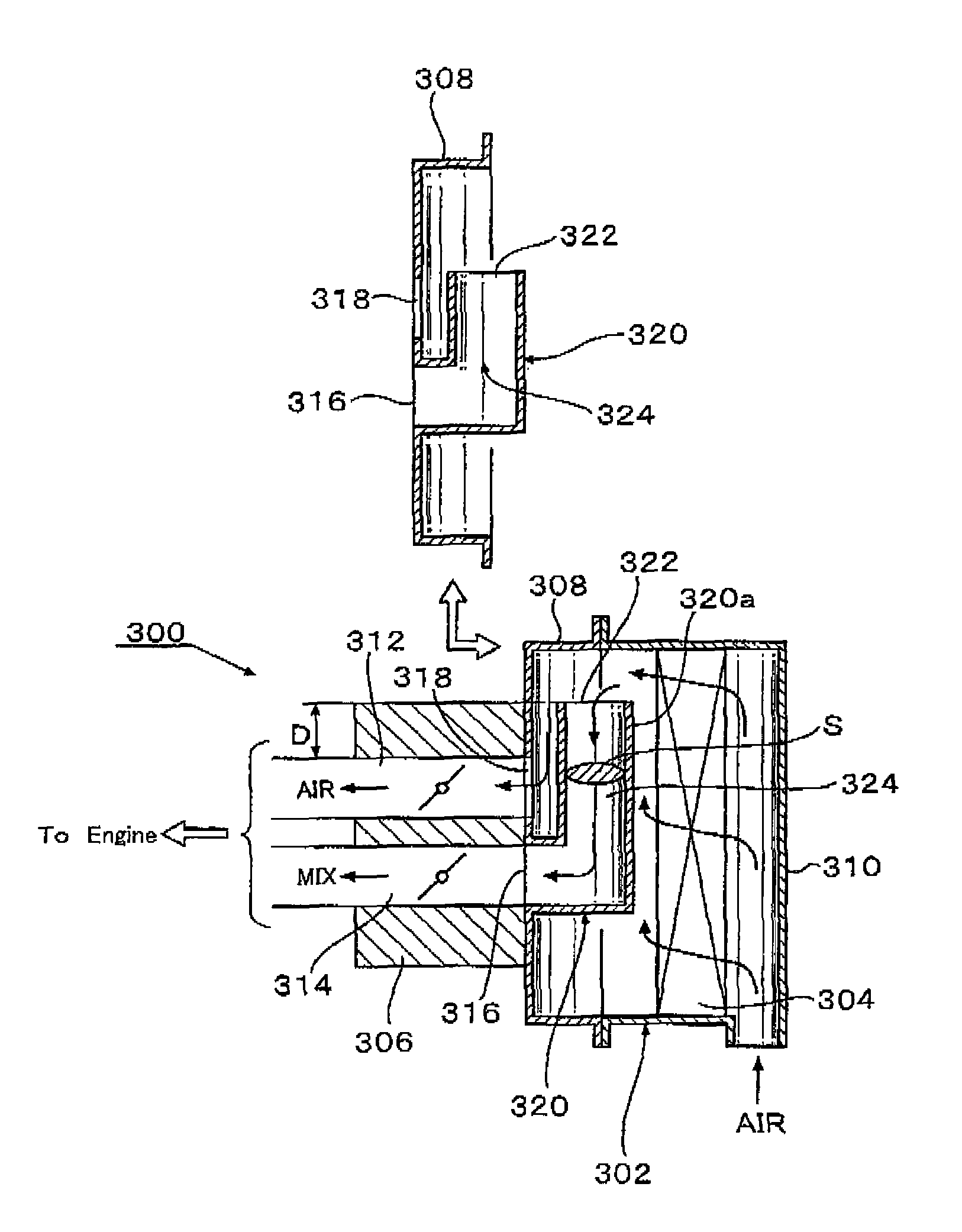
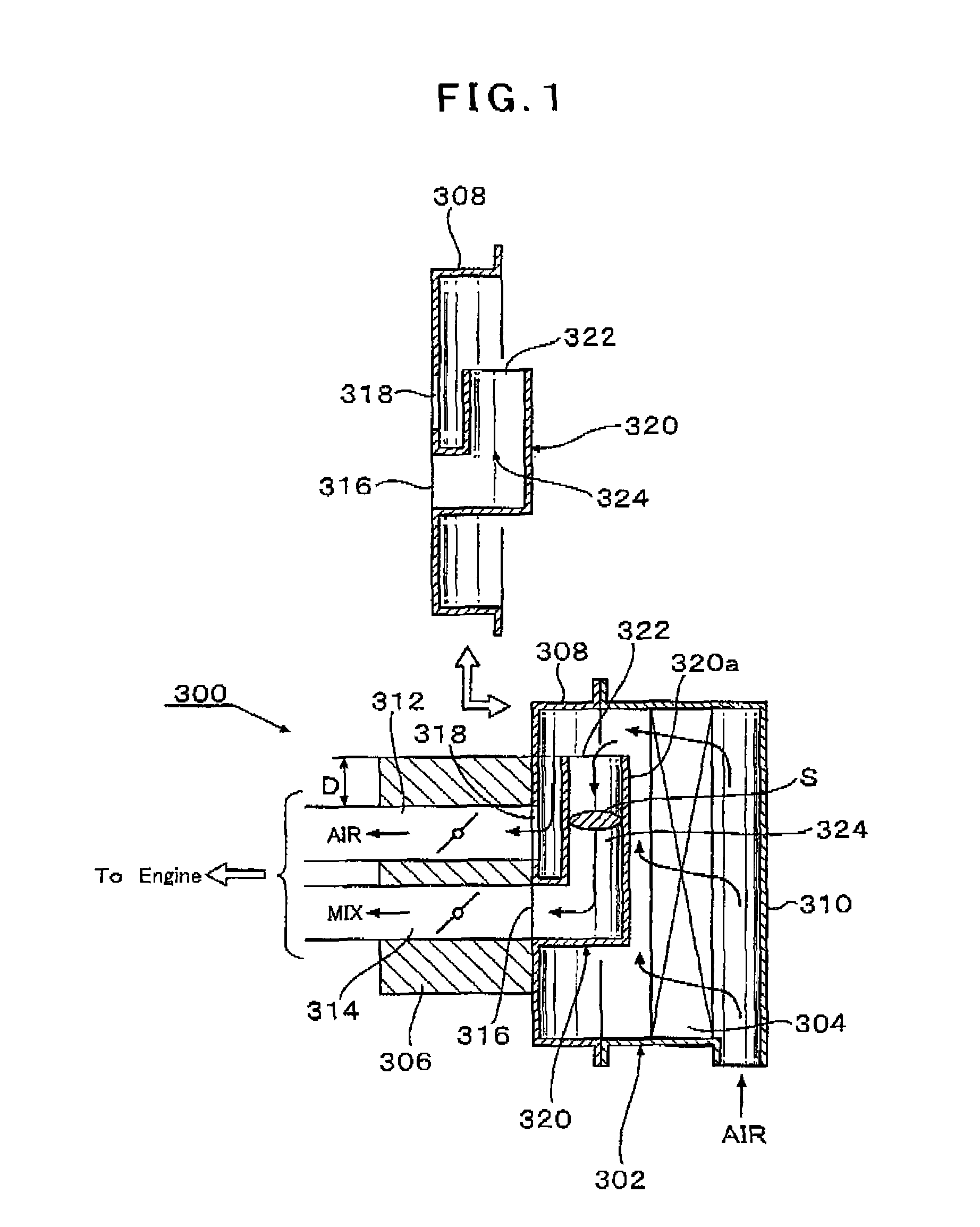
[0020]Blown-back gas from the air-fuel mixture passage 314 of the carburetor 306 is checked at the curved portion of the air guide member 320 because of the curved passage configuration of the air guide member 320. Thus, the blown-back gas is prevented from flowing externally from the first clean air intake 322 of the air guide member 320 and from leaking into the air cleaner 302. Accordingly, the fuel component in the blown-back gas is restricted to intrude into the fresh air passage 312 of the carburetor 306 through the fresh air opening 318 of the air cleaner base 308. Thereby, harmful emissions in the exhaust gas from the two-stroke internal combustion engine can be reduced.
[0021]To reduce the undesirable flow of the fuel component in the blown-back gas into the fresh air opening 318 of the air cleaner base 308, the first clean air intake 322 of the air guide member 320 is preferably disposed apart from the fresh air opening 318 of the air cleaner base 30. In other words, it is preferable to design these members to reserve a long distance D between the first clean air intake 322 and the fresh air opening 318.
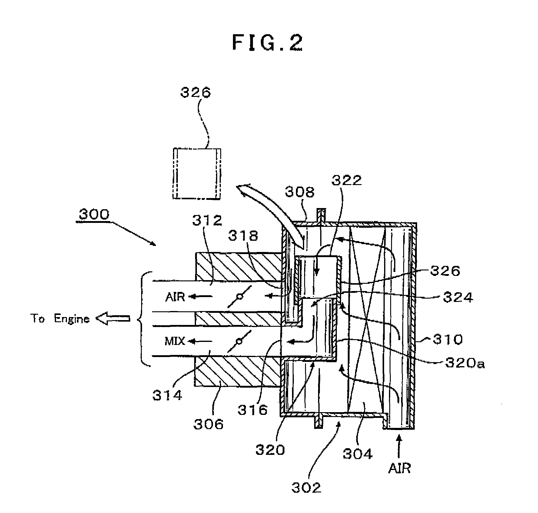
[0023]For the benefit of the concept of providing a two-stroke internal combustion engine of particular engine characteristics in accordance with a users request by a simple manner of tuning the length of the mixture-use air extension passage 324 of the air guide member 320, various modifications that make it very easy to tune the engine characteristics can be proposed as shown in FIGS. 2 to 4.

Problems solved by technology

As such, the two-cycle engines are configured to scavenge the combustion chamber by using flows of air-fuel mixture, and therefore involve the problem of “blow-by”.
That is, a part of the air-fuel mixture, introduced into the combustion chamber and having not burnt, is undesirably discharged away from the combustion chamber together with a combustion gas.
This “blow-by” phenomenon makes it difficult to take effective measures for emissions cut of two-stroke engines.
However, as pointed out in Document 2, air-fuel mixture partly pushed back into the air cleaner due to “blow-back” from the air-fuel mixture passage of the carburetor flows into the air passage, thereby causing the fuel to mix with fresh air for use in initial scavenging.
This will invite the problem that an unburnt component is discharged from the engine together with combustion gas.
Needless to say, this is one of technical problems to be improved in the recent society under an increased request for cleaning or purifying exhaust gas.

Method used


Image

  • Air cleaner for two-stroke internal combustion engine and method of tuning the length of air-fuel mixture passage by using the air cleaner
  • Air cleaner for two-stroke internal combustion engine and method of tuning the length of air-fuel mixture passage by using the air cleaner
  • Air cleaner for two-stroke internal combustion engine and method of tuning the length of air-fuel mixture passage by using the air cleaner

Examples


first embodiment

FIGS. 17 to 23

[0096]With reference to FIG. 17, the air cleaner 55 includes an air cleaner base 61 and an outer case 62 that, in combination, define an air cleaner chamber 66 (FIG. 16). An air cleaner element 67 composed of a lower element 63 and an upper element 64 is held in a predetermined position within the air cleaner chamber 66. Filters 63a, 64a that may be plastic molded nets, meshed fabric, or paper sheets having fine bores, and held on frames 63b, respectively, are fixed to the lower element 63 and the upper element 64.

[0097]The air cleaner base 61 is detachably connected to the upstream end of the carburetor 54 by bolts (not shown). With reference to FIG. 17, the air cleaner base 61 has an air-fuel mixture opening 70 enclosed by an upright tubular circumferential flange 69. The air-fuel mixture opening 70 is disposed in alignment with a position of the air-fuel mixture passage 54b of the carburetor 54. Although both the air-fuel mixture opening 70 and the circumferential f...

second embodiment

FIG. 24

[0122]The second embodiment is directed to an air cleaner in which the air guide member 65 is partly defined by the lower element 63. The lower element 63, in combination with the upper element 84 (FIG. 17), defines the air cleaner element, and the lower element 63 has a second tubular boss 80 corresponding to the first tubular boss 71 (communicating with the fresh air passage 54a of the carburetor 54) of the air cleaner base 61 and a first inlet 83 communicating with the air-fuel mixture opening 70 (communicating with the air-fuel mixture passage 54b of the carburetor 54) of the air cleaner base 61.

[0123]In this embodiment the lower element 63 has a bottom wall 100 extending in a bilateral direction with respect to the first inlet 83 in a U-shaped geometry in its plan view, and the bottom wall 100 has first flanges 100a along its both side edges. The bottom wall 100 defines a part of the air guide member 65.

[0124]That is, in this embodiment, the air guide member 65 is compos...

third embodiment

FIG. 25

[0127]The third embodiment is directed to an air cleaner 55 having a modified air cleaner element 67. The air cleaner element 67 used here has a shape of a ring as a whole. The ring-shaped air cleaner element 67 is assembled in the air cleaner 55 in a configuration sandwiched between the air cleaner base 61 and a top plate 122 that are spaced apart from each other. Then, a cover 124 is assembled to cover the entirety of the air cleaner base 61, air cleaner element 67 and top plate 122. Note that the air guide member 65 used in the third embodiment is a tubular member curved in an L-shaped geometry when viewed in a side elevation, and the L-shaped tubular member 65 is in detachable fitting engagement with the circumferential flange 69 around the air-fuel mixture opening 70 of the air cleaner base 61.


PUM

PropertyMeasurementUnit
angleaaaaaaaaaa
lengthaaaaaaaaaa
lengthsaaaaaaaaaa

Abstract

An air cleaner is used in a two-stroke internal combustion engine to supply an air-fuel mixture passage and a fresh air passage in a carburetor with air cleaned by an air cleaner element. The air cleaner includes an air cleaner base having an air-fuel mixture opening communicating with the air-fuel mixture passage and a fresh air opening communicating with the fresh air passage, and an air guide member provided at the air-fuel mixture opening. The air guide member is configured to curve near the air-fuel mixture opening and extend from there along the air cleaner base, and has a cross section surrounded by a peripheral wall. The air guide member defines a mixture-use air extension passage for air to be added to prepare an air-fuel mixture air-fuel mixture, which extends from a first clean air intake to the air-fuel mixture opening. Blown-back gas from the air-fuel mixture passage hits against the inner wall of the curved portion of the air guide member, and is therefore restricted to flow out of the first clean air intake and leak into the air cleaner. Thereby, harmful emissions in the exhaust gas from the two-stroke internal engine can be reduced.

Description

[0001]The present application claims priority from Japanese Patent Application No. 2006-321626, filed Nov. 29, 2006, and Japanese Patent Application No. 2007-105554, filed Apr. 13, 2007, which are incorporated herein by reference.FIELD OF THE INVENTION[0002]The present invention generally relates to two-stroke internal combustion engines. More particularly, the present invention relates to an air cleaner for such engines used as a power source of portable power working machines such as chain saws and brush cutters, and to a method of tuning the length of an air-fuel mixture passage by using the air cleaner.BACKGROUND OF THE INVENTION[0003]Two-stroke gasoline engines have been used as a power source of portable power working machines such as brush cutters, chain saws or the like. In a two-stroke internal combustion engine of this type, a combustion chamber is scavenged by a flow of air-fuel mixture pre-compressed in a crank chamber. More specifically, as the piston ascends, the air-f...

Claims


Application Information

Patent Timeline
Patent Type & Authority Patents(United States)
IPC IPC(8): B01D46/00
CPCB01D46/0002F02B25/22F02B27/02F02B33/04F02B33/44F02M17/34F02M19/00F02M35/024F02M35/04F02M35/1017F02M35/1019F02M35/10196F02M35/108B01D2279/60F02M35/02Y02T10/146F02B27/003F02B27/005F02B27/0215F02B27/0236Y02T10/12Y10S55/28
Inventor SATO, SHIGERUKAWAMURA, KUNIMUNETSUNODA, HIDEKAZUTSUTSUI, KAZUHIRO
Owner YAMABIKO CORP
Why Eureka
Eureka Blog
Learn More