Magnetic carrier and two-component developer

a technology of magnetic carrier and developer, applied in the field of magnetic carrier and two-component developer, can solve the problems of large image density variation, low electrical resistance of magnetic carrier, coarse halftone areas, etc., and achieve the effect of stable developing performance and less variation in image density

Active Publication Date: 2010-12-28
CANON KK
View PDF17 Cites 56 Cited by
  • Summary
  • Abstract
  • Description
  • Claims
  • Application Information

AI Technical Summary

Benefits of technology

[0012]Another object of the present invention is to provide a magnetic carrier and a two-component developer which enable formation of high-quality images over a long period of time.
[0013]Still another object of the present invention is to provide a magnetic carrier and a two-component developer which can achieve stable developing performance and may cause less variation in image density, over a long period of time, and can keep blank areas and carrier sticking from occurring and keep fog from occurring even after long-term storage in a high-temperature and high-humidity environment.
[0016]The use of the magnetic carrier and two-component developer of the present invention enables image defects to be kept from occurring and enables high-quality images to be obtained over a long period of time.

Problems solved by technology

Also, because of its coat resin layers designed to be small in thickness, it has come about that the magnetic carrier becomes low in electrical resistance because of scrape-off of the coat resin.
Still also, the coat resin binds directly with spherical ferrite cores, and hence the coat resin and the cores may have an insufficient adherence between them, so that the coat resin may come to come off to make the magnetic carrier have a low electrical resistance.
In such a case, especially when the two-component developer is left to stand for a long term in a high-temperature and high-humidity environment after long-term service, it may cause fog or great image density variations.
In addition, a phenomenon that electric charges are injected from a developing sleeve into an electrostatic latent image bearing member through the magnetic carrier may come about to disturb latent images on the electrostatic latent image bearing member to make halftone areas coarse.
However, it may make the toner have a low developing performance.
As the result, the toner at the rear end of a halftone area may come scraped off at the boundary between a halftone image area and a solid image area to make white lines, to cause image defects in which edges of solid image areas stand emphasized (hereinafter “blank areas”).
However, it may make the toner have an inferior developing performance.
As the result, like the above, the toner at the rear end of a halftone area may come scraped off at the boundary between a halftone area and a solid area to make white lines, to cause image defects in which edges of solid areas stand emphasized (hereinafter “blank areas”).
In this case, however, a phenomenon of faulty images may occur in which ring-like or spot-like patterns appear on recording sheets.
As the magnetic carrier becomes higher in electrical resistance, counter charges having come accumulated on the magnetic carrier particles become difficult to move to the developer carrying member side.
Hence, any counter charges remaining on the magnetic carrier particle surfaces and the electric charges of the toner may attract each other to produce a large adhesion, so that the toner may become difficult to fly from the magnetic carrier particles, resulting in a low image density.

Method used


Image

  • Magnetic carrier and two-component developer
  • Magnetic carrier and two-component developer
  • Magnetic carrier and two-component developer

Examples


example 1

[0378]To 92 parts by mass of Magnetic Carrier 1, 8 parts by mass of Toner A was added, and these were put to shaking for 10 minutes by means of a V-type mixing machine to prepare a two-component developer. Using this two-component developer, the following evaluations were made. The results of evaluations are shown in Table 6.

[0379]A conversion machine of a digital copying machine iRC3580, manufactured by CANON INC., was used as an image forming apparatus. The above developer was put into its developing assembly at the cyan position, and images were formed in a normal-temperature and normal-humidity (temperature 23° C. / humidity 50% RH) environment. An AC voltage of 2.0 kHz in frequency and 1.3 kV in Vpp and a DC voltage VDC were applied to the developing sleeve. The DC voltage VDC was controlled to 500 V under such a condition that the Vback was fixed at 150 V. Color Laser Copier Paper (A4, 81.4 g / m2, available from CANON INC.) was used as transfer materials. Under the above conditio...

example 10

[0531]To 92 parts by mass of Magnetic Carrier 18, 8 parts by mass of Toner D was added, and these were put to shaking for 10 minutes by means of a V-type mixing machine to prepare a two-component developer. Using this two-component developer, the following evaluations were made.

[0532]The results of evaluations are shown in Table 12. A conversion machine of a digital printer for business use IMAGEPRESS C7000VP, manufactured by CANON INC., was used as an image forming apparatus. The above developer was put into its developing assembly at the cyan position, and images were formed in a normal-temperature and normal-humidity (temperature 23° C. / humidity 50% RH) environment. As conversion points, the developing sleeve was so converted that its peripheral speed was 1.5 times that of the photosensitive member and also a discharge opening of the replenishing developer was closed so that only the toner was replenished. Then, an AC voltage of 2.0 kHz in frequency and 1.3 kV in Vpp and a DC vol...


PUM


Abstract

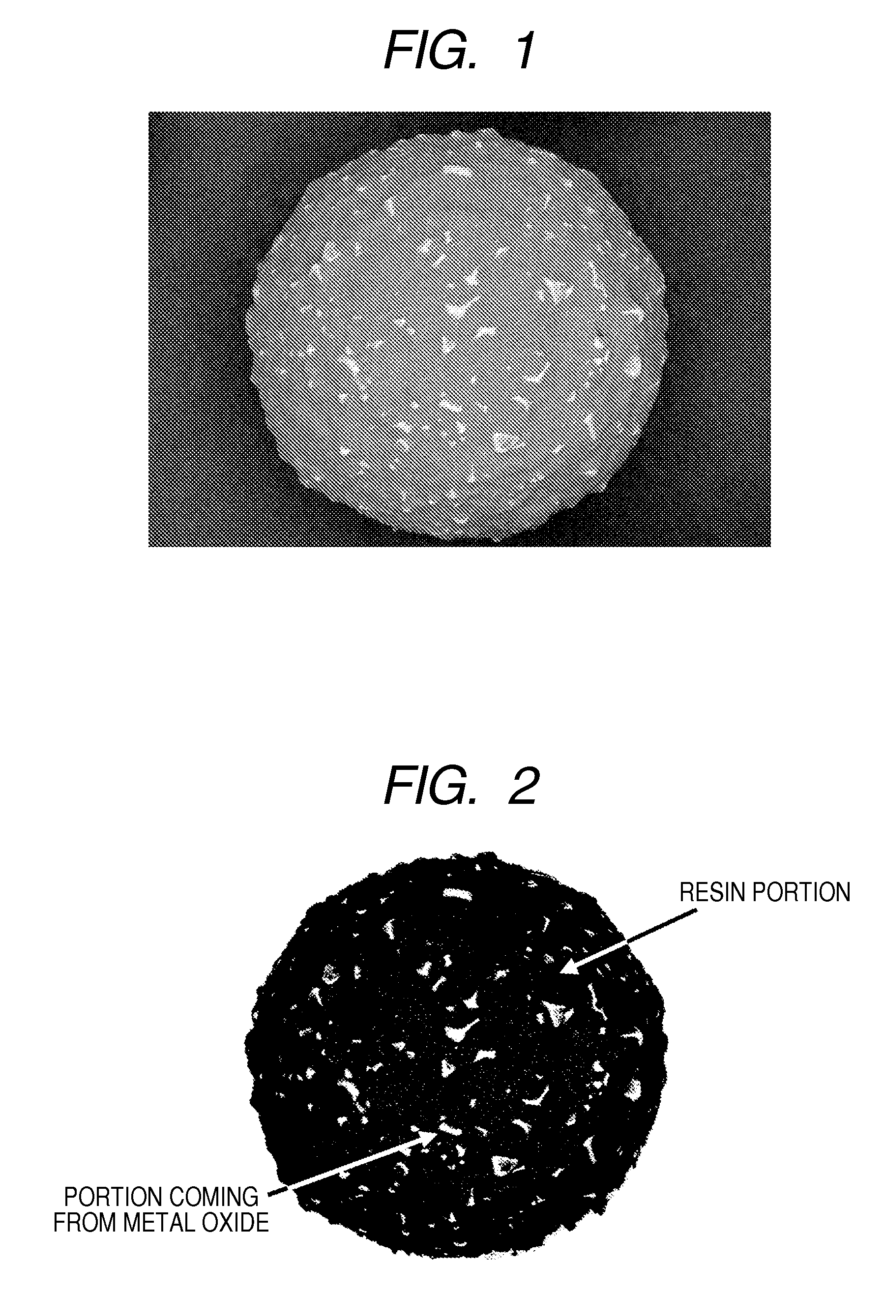
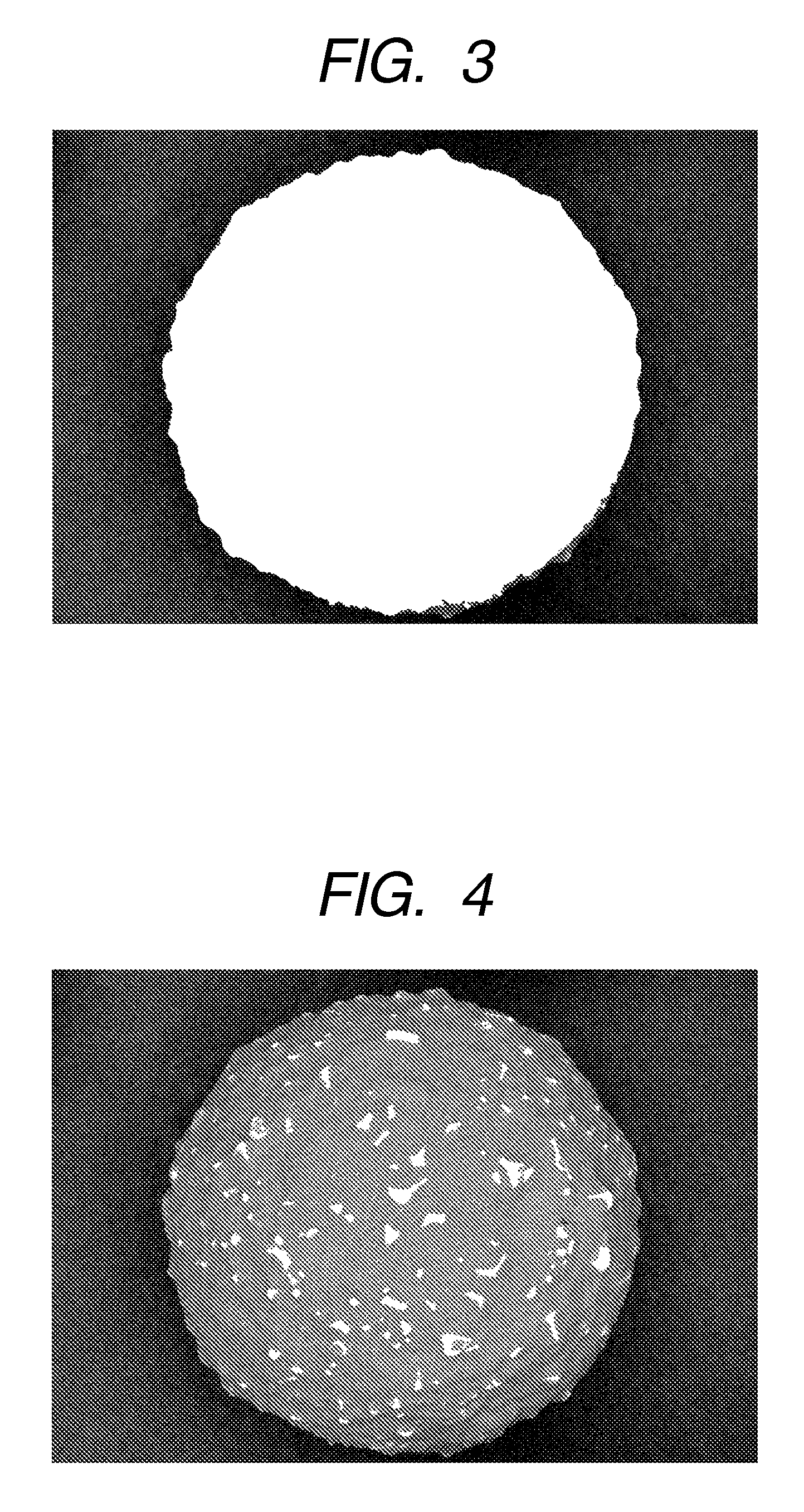
A magnetic carrier which has magnetic carrier particles each having at least porous magnetic core particles and a resin, in which, in a backscattered electron image of the magnetic carrier particles, photographed with a scanning electron microscope as taken at an accelerating voltage of 2.0 kV, magnetic carrier particles having area proportion S1 found from a specific expression (1) of from 0.5 area % or more to 8.0 area % or less are in a proportion of 8.0% by number or more in the magnetic carrier, an average proportion Av1 of the total area of portions having a high luminance which come from a metal oxide on the magnetic carrier particles to the total projected area of the magnetic carrier particles is from 0.5 area % or more to 8.0 area % or less, and an average proportion Av2 found from a specific expression (2) is 10.0 area % or less.

Description

[0001]This application is a continuation of International Application No. PCT / JP2009 / 064089, filed Aug. 4, 2009, which claims the benefit of Japanese Patent Application No. 2008-201074, filed Aug. 4, 2008.BACKGROUND OF THE INVENTION[0002]1. Field of the Invention[0003]This invention relates to a magnetic carrier contained in a developer used in electrophotography and electrostatic recording, and a two-component developer having this magnetic carrier and a toner.[0004]2. Description of the Related Art[0005]Developing systems of electrophotography include a one-component developing system, which makes use of a toner only, and a two-component developing system, which makes use of a toner and a magnetic carrier in blend. In the two-component developing system, a magnetic carrier that is a charge-providing member and a toner are blended and used as a two-component developer. The two-component developer provides so many opportunities of contact between the charge-providing member magnetic...

Claims


Application Information

Patent Timeline
Patent Type & Authority Patents(United States)
IPC IPC(8): G03G9/113G03G9/08
CPCG03G9/107G03G9/1075G03G9/1131G03G9/1136G03G9/1139G03G9/1085G03G9/08G03G9/113
Inventor ISHIGAMI, KOHFUJIKAWA, HIROYUKINAKAMURA, KUNIHIKOKOMATSU, NOZOMUINOUE, CHIKAENDO, TOMOKOBABA, YOSHINOBUITAKURA, TAKAYUKI
Owner CANON KK
Why Eureka
Try Eureka