Stepper motor apparatus and method for controlling stepper motor

a stepper motor and stepper motor technology, applied in the direction of electric controllers, dynamo-electric converter control, instruments, etc., can solve the problems of inaccuracy of indication, mechanical obstruction of magnetic rotor, and variation of indication of pointer

Active Publication Date: 2010-12-28
YAZAKI CORP
View PDF2 Cites 2 Cited by
  • Summary
  • Abstract
  • Description
  • Claims
  • Application Information

AI Technical Summary

Benefits of technology

[0017]In accordance with the first embodiment of the stepper motor apparatus, because the forward driving device is configured to feed the driving signal into the stepper motor in order to drive the stepper motor to rotate in the forward direction where the driven member is driven against the stopper, after first stop by the first stopping device, the second stopping device is configured to stop rotation of the stepper motor in the forward direction by maintaining the predetermined phase when the driving signal transmitted by the forward driving device arrives at the predetermined phase, and the normal driving device drives the stepper motor to rotate again after second stop by the second stopping device, it is possible to begin to rotate the stepper motor at the predetermined phase (i.e., at the same position) by means of the normal driving device, even if a change in the position where the protrusion is in abutment with the stopper occurs depending on the aged deterioration or the thermal expansion of each components comprising the stepper motor apparatus due to, for example, a change in ambient temperature.
[0023]In accordance with the afore-mentioned embodiment of the method for controlling the stepper motor, because between the step (C) and the step (D), the step of feeding the driving signal into the stepper motor in order to drive the stepper motor to rotate in the forward direction where the driven member is driven against the stopper, and subsequently, the step of stopping rotation of the stepper motor in the forward direction by maintaining the predetermined phase when the driving signal arrives at the predetermined phase stored in a memory are carried out in stepwise fashion, it is possible to begin to rotate the stepper motor at the predetermined phase (i.e., at the same position) by means of the normal driving device, even if a change in the position where the driven member is in abutment with the stopper occurs depending on the aged deterioration or the thermal expansion of each components comprising the stepper motor apparatus due to, for example, a change in ambient temperature.

Problems solved by technology

Meanwhile, during the indicator, due to the input of the value measured by means of a variety of sensors which vibration or noise of vehicles can adversely affect, the actual movement of the pointer may be different from its measured movement, i.e., (θ−θ′).
If this phenomenon is repeated, the actual position θ stored in memory can be different from the position displayed on the dial, resulting in an inaccurate indication.
On the other hand, when the voltage level is lower than a threshold voltage level, the induced voltage is hardly generated, and the magnetic rotor is found to be obstructed mechanically by the stopper being in abutment with the protrusion.
Therefore, when the output of the driving signal corresponding to the amount of difference (θ−θ′) is intended from the phase of the driving signal at the point of detecting that the protrusion is in abutment with the stopper, a problem occurs that the indication of the pointer may be varied depending on the aged deterioration or the thermal expansion of each components comprising the stepper motor apparatus due to a change in ambient temperature.

Method used


Image

  • Stepper motor apparatus and method for controlling stepper motor
  • Stepper motor apparatus and method for controlling stepper motor
  • Stepper motor apparatus and method for controlling stepper motor

Examples


Embodiment Construction

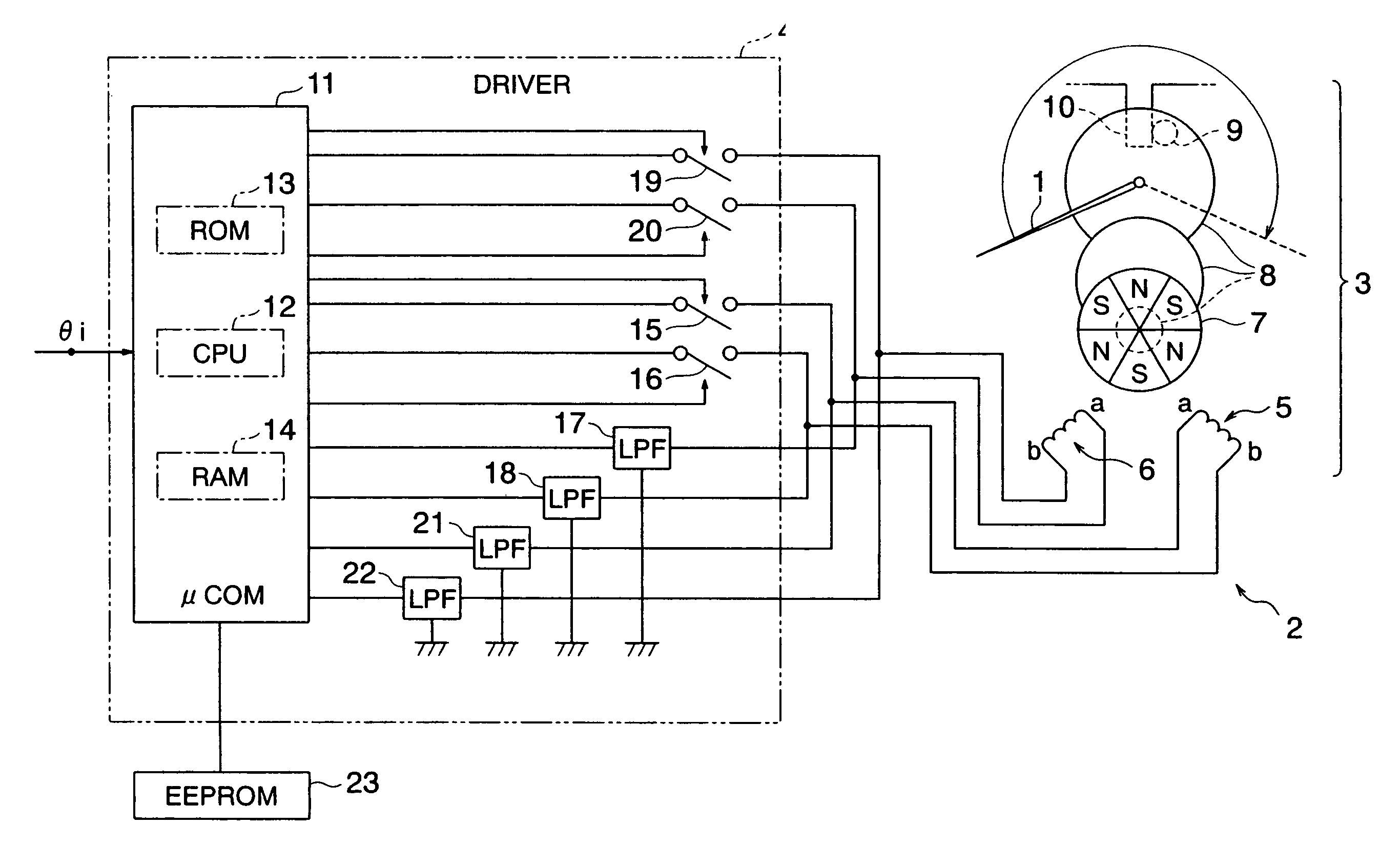
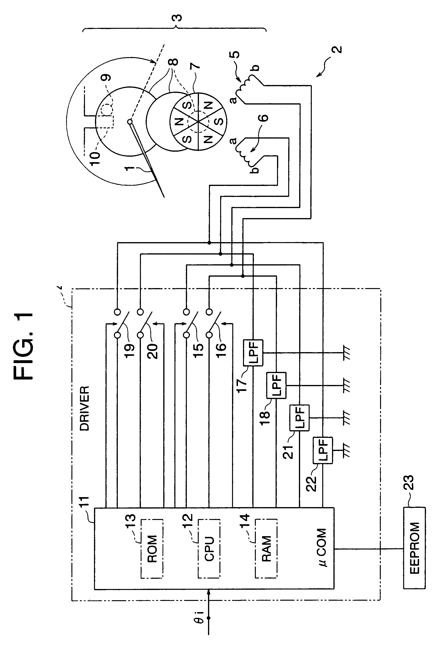
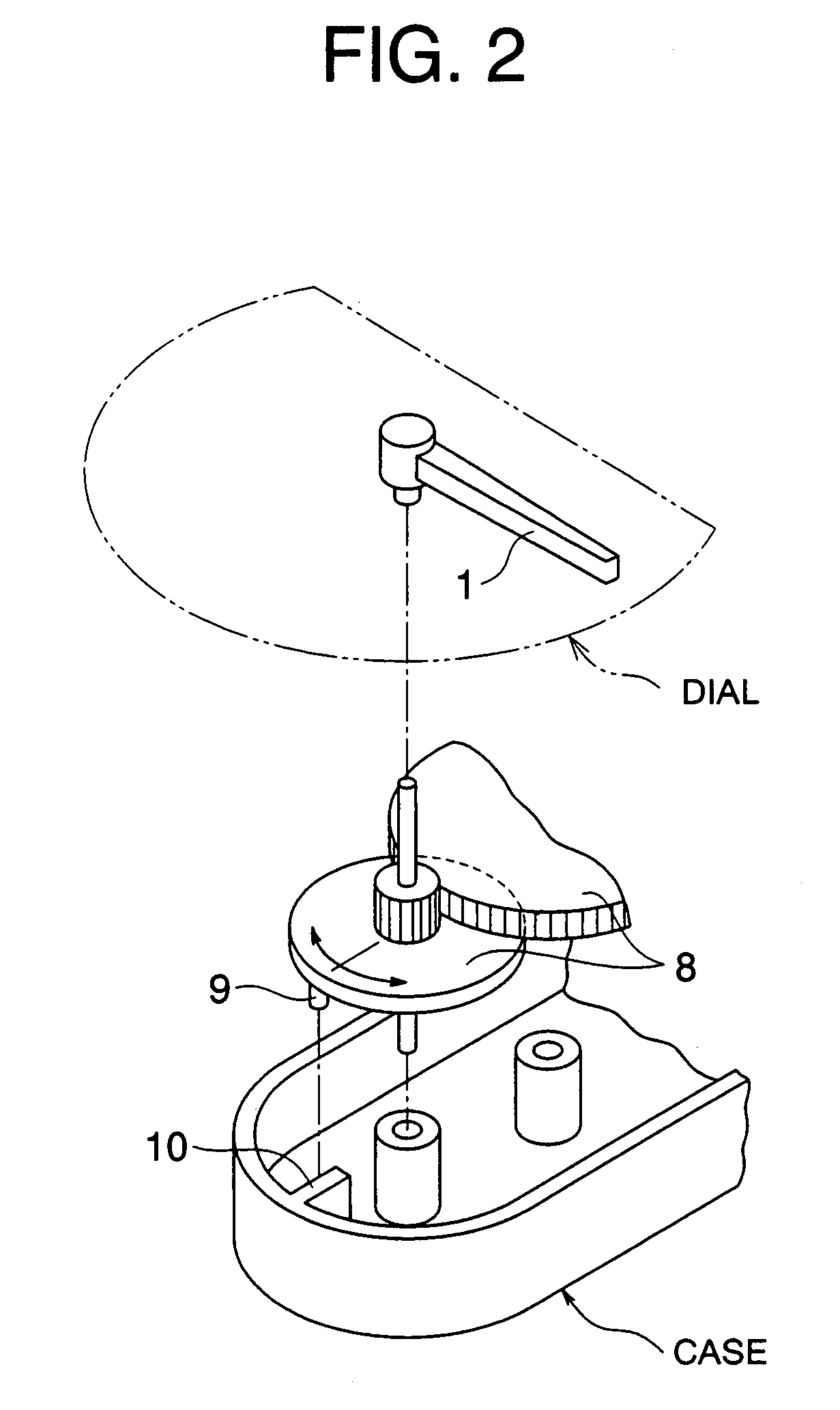
[0038]Referring to FIG. 1, there is provided a circuit diagram illustrating an indicator equipped with a stepper motor apparatus for implementing a method for driving the stepper motor in accordance with an embodiment of the present invention. FIG. 2 is an exploded perspective view of the indicator of FIG. 1. The indicator is comprised of a pointer 1, and a stepper motor apparatus 2 configured to drive the pointer 1. The pointer 1 is located on a dial with the scale of the value measured by a sensor device such as a speedometer. (Refer to FIG. 2)

[0039]The stepper motor apparatus 2 comprises a stepper motor 3, and a driver 4 for rotating the stepper motor 3. The stepper motor 3 comprises two excitation coils 5 and 6, a magnetic rotor 7 which rotates depending on a change in excitation state of the excitation coils 5 and 6, a gear assembly 8 configured to input a driving force to the pointer 1, and a case.

[0040]The magnetic rotor 7 is disc-like, and has three pairs of poles (e.g. thre...


PUM


Abstract

The object of the invention is to provide a stepper motor apparatus and a method for controlling a stepper motor, and particularly relates to a stepper motor apparatus for driving a pointer and a method for controlling the stepper motor. When an ignition switch is turned on, CPU 12 starts to feed a driving signal into the stepper motor in order to cause the stepper motor to rotate in a backward direction. Upon detecting that a protrusion 9 is in abutment with a stopper 10 on the basis of induced voltage generated on excitation coils 5 and 6, CPU stop rotation of the stepper motor 3 by maintaining the driving signal's phase at which the abutment is detected. Subsequently, CPU 12 feeds the driving signal into the stepper motor 3 in order to drive the stepper motor 3 to rotate in a direction where the protrusion 9 is driven against the stopper 10, and then stops rotation of the stepper motor 3 in a forward direction by maintaining a predetermined phase at which the driving signal arrives. Thereafter, CPU 12 drives the stepper motor to rotate such that a pointer 1 homes in on its commanded position θi.

Description

CROSS-REFERENCE TO RELATED APPLICATIONS[0001]The present Application claims priority to Japanese Patent Application No. 2006-173874 filed Jun. 23, 2006, the entire disclosure of which, including the specification and drawings, is expressly incorporated herein by reference.BACKGROUND OF THE INVENTION[0002](1) Field of the Invention[0003]The present invention relates to a stepper motor apparatus and a method for controlling a stepper motor, and particularly relates to a stepper motor apparatus for driving a pointer and a method for controlling the stepper motor.[0004](2) Description of the Related Art[0005]Conventionally, a stepper motor apparatus has been found to be suitable for use in, for example, an automotive dashboard indicator. The indicator includes a dial having graphical indicia and a pointer which is driven around the dial. The stepper motor apparatus has been used as a device for driving the pointer.[0006]This type of stepper motor apparatus provides a driving signal a du...

Claims


Application Information

Patent Timeline
Patent Type & Authority Patents(United States)
IPC IPC(8): H02P8/00
CPCG01R7/06H02P8/34G01D2213/10
Inventor YAMADA, YOSHIHISA
Owner YAZAKI CORP
Why Eureka
Try Eureka