Antenna pattern and electromagnetic-wave energy processing device having the same
a technology of electromagnetic wave energy processing and antenna pattern, which is applied in the direction of waveguide type devices, substantially flat resonant elements, resonance antennas, etc., can solve the problems of severe social problems, unsatisfactory clear display images, etc., and achieve clearer and more stable images, improve directivity, and improve image clarity
- Summary
- Abstract
- Description
- Claims
- Application Information
AI Technical Summary
Benefits of technology
Problems solved by technology
Method used
Image
Examples
example 1
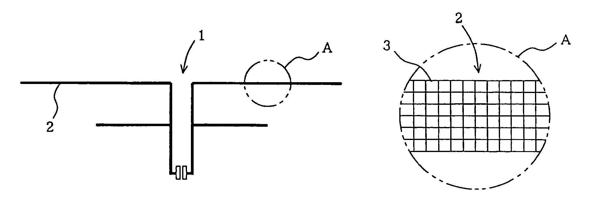
[0058]FIG. 1 is a diagram showing an antenna pattern in Example 1 of the present invention.
[0059]FIG. 2 is an enlarged reference diagram of a portion A in FIG. 1, showing an example where the aggregated wire consists of lattice type mesh micro-image element lines.
[0060]In the drawings, the reference numeral 1 represents an antenna pattern; 2, a conductor wire; and 3, mesh micro-image element lines.
[0061]The antenna pattern in Example 1 was formed to be 2 mm in width of a conductor wire, 39 cm in length of a long wire portion, 25 cm in length of a short wire portion and 3 cm in interval between the two wires, while the conductor wire was formed as an aggregated wire having a lattice type mesh pattern. The line width was set to be 20 μm and the line pitch interval was set to be 100 μm. The antenna pattern was printed by offset printing with synthetic ink mixed with Pd powder having an average particle size of 1 μm. Cu-plating about 1 μm thick was performed upon the printed surface by ...
example 2
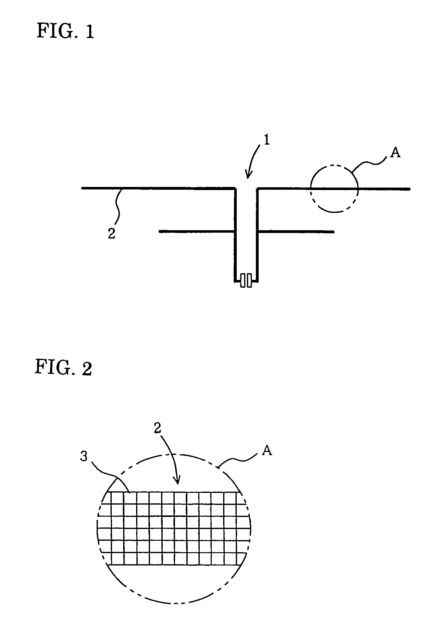
[0065]FIG. 3 is an enlarged reference diagram of a portion A in Example 2 of the present invention, showing an example where the aggregated wire consists of continuously polygonal micro-image element lines.
[0066]In the drawing, the reference numeral 4 represents a continuously polygonal micro-image element lines.
[0067]In the same manner as in Example 1, the antenna pattern in Example 2 was formed to be 2 mm in width of a conductor wire, 39 cm in length of a long wire portion, 25 cm in length of a short wire portion and 3 cm in interval between the two wires, while the conductor wire was formed as an aggregated wire having a lattice type mesh pattern. The line width was set to be 20 μm, and the pitch between opposite sides of each continuous polygonal shape was set to be 100 μm. The antenna pattern was printed by offset printing with synthetic ink mixed with Pd powder having an average particle size of 1 μm. Cu-plating about 1 μm thick was performed upon the printed surface by electr...
example 3
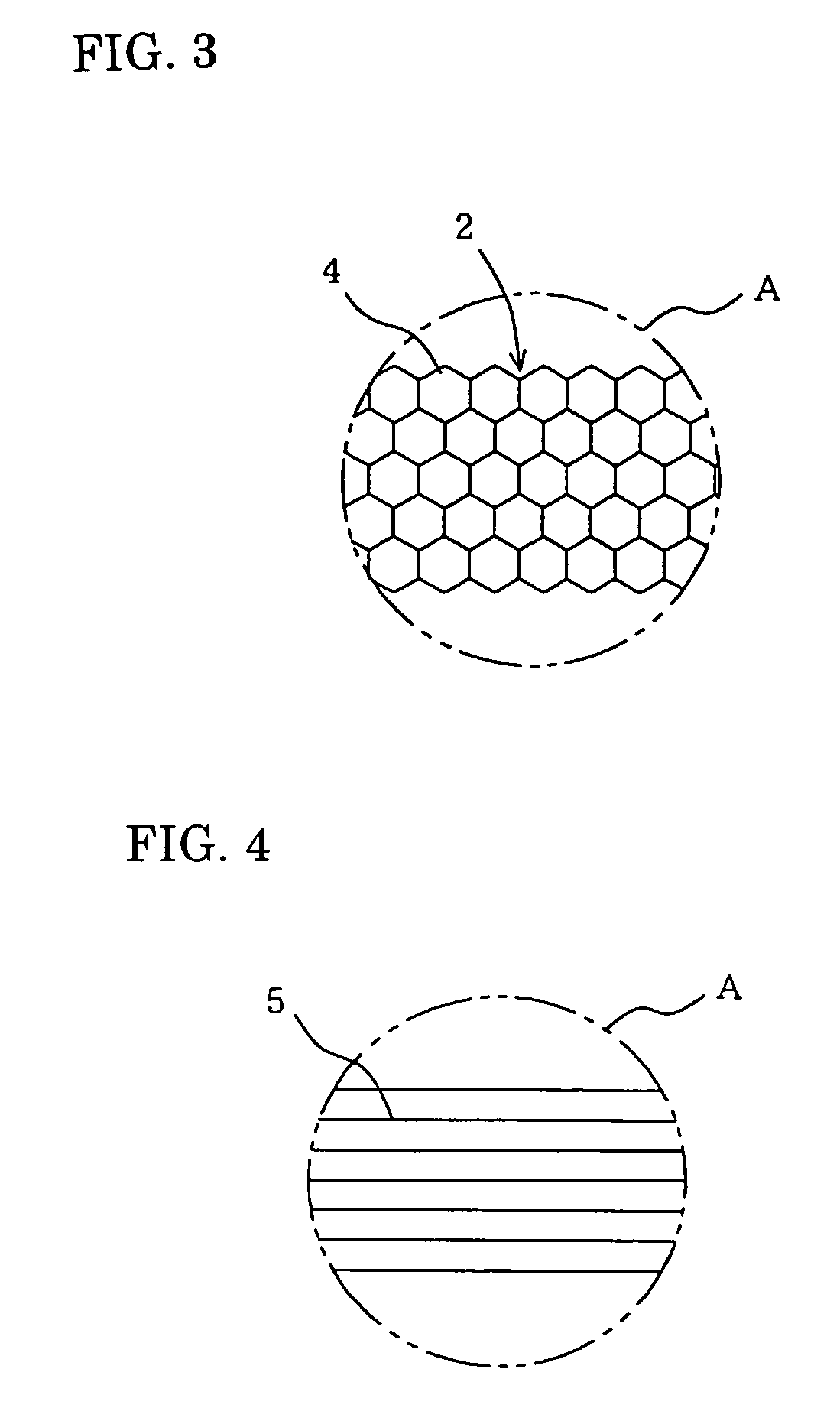
[0071]FIG. 4 is an enlarged reference diagram of a portion A in Example 3 of the present invention, showing an example where the aggregated wire consists of parallel aggregated lines.
[0072]In the drawing, the reference numeral 5 represents a parallel aggregated lines like a straight lines.
[0073]In the same manner as in Example 1, the antenna pattern in Example 3 was formed to be 2 mm in width of a conductor wire, 39 cm in length of a long wire portion, 25 cm in length of a short wire portion and 3 cm in interval between the two wires, while the conductor wire was formed as a parallel aggregated wire. The line width was set to be 20 μm, and the line pitch was set to be 100 μm. The antenna pattern was printed by offset printing with synthetic ink mixed with Pd powder having an average particle size of 1 μm. Cu-plating about 1 μm thick was performed upon the printed surface by electroless plating.
[0074]For the sake of comparison, an antenna pattern with the same pattern, in which the a...
PUM
 Abstract
Description
Claims
Application Information
 - R&D
- Intellectual Property
- Life Sciences
- Materials
- Tech Scout
- Unparalleled Data Quality
- Higher Quality Content
- 60% Fewer Hallucinations
Browse by: Latest US Patents, China's latest patents, Technical Efficacy Thesaurus, Application Domain, Technology Topic, Popular Technical Reports.
© 2025 PatSnap. All rights reserved.Legal|Privacy policy|Modern Slavery Act Transparency Statement|Sitemap|About US| Contact US: help@patsnap.com


