
Hearing device and method for reducing feedback therein

a technology of hearing device and feedback, which is applied in the direction of hearing aid vents, deaf-aid sets, electric devices, etc., to achieve the effect of low feedback tendency

Inactive Publication Date: 2010-12-28
SIVANTOS PTE LTD
View PDF13 Cites 2 Cited by
  • Summary
  • Abstract
  • Description
  • Claims
  • Application Information

AI Technical Summary

Benefits of technology

This configuration allows for simultaneous achievement of open feed, utilization of the natural pinna directional effect, and a low feedback tendency, enabling effective sound separation and reduction of feedback.

Problems solved by technology

Due to the relatively high variability and complexity of the feedback path, the effect is conventionally limited to approximately 10 dB to a maximum of 15 dB amplifier gain.

Method used


Image

  • Hearing device and method for reducing feedback therein
  • Hearing device and method for reducing feedback therein
  • Hearing device and method for reducing feedback therein

Examples


Embodiment Construction

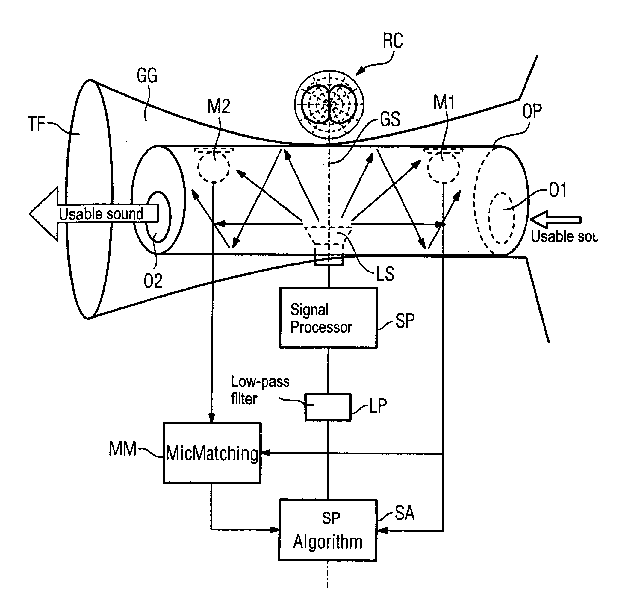
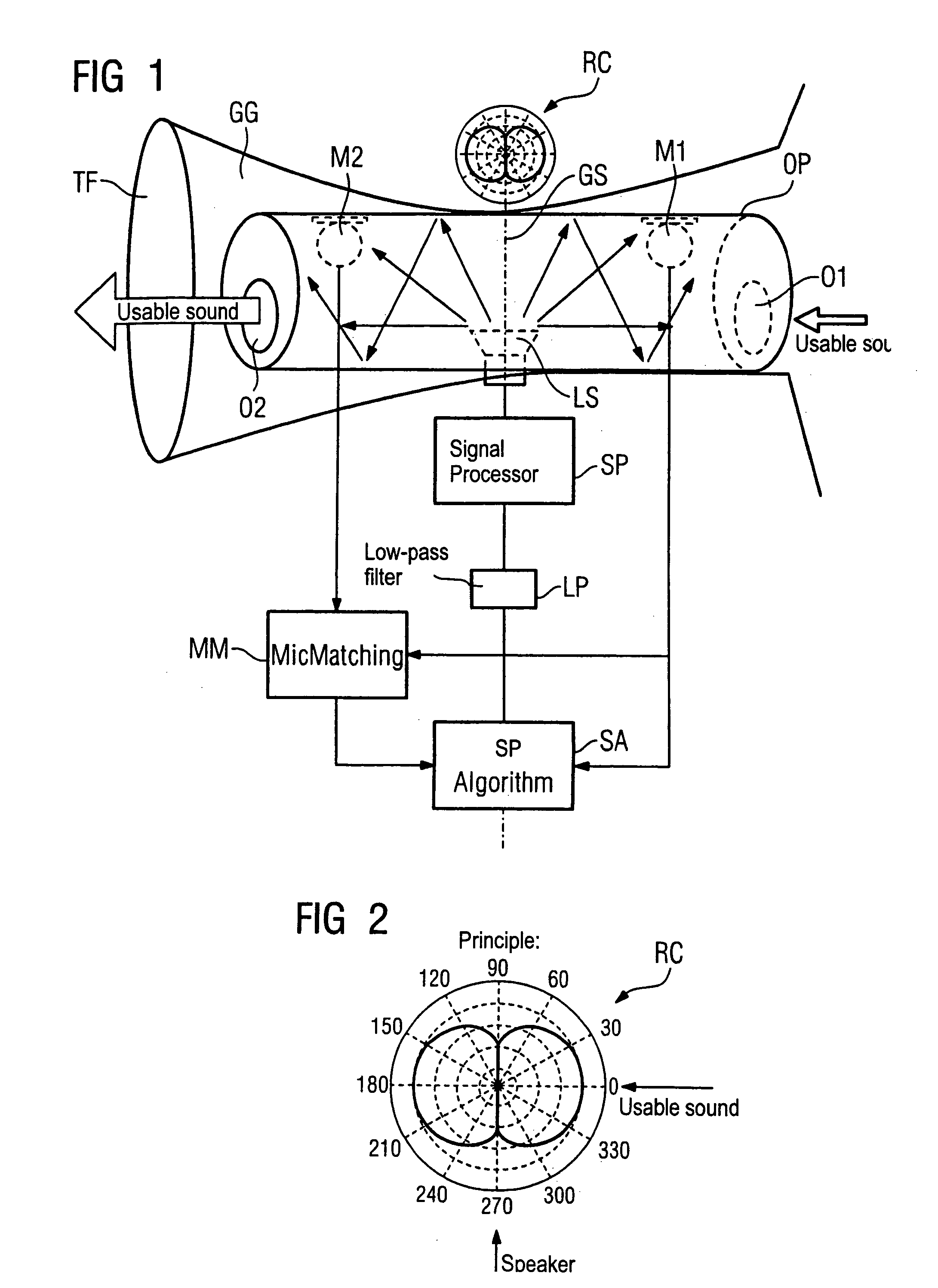
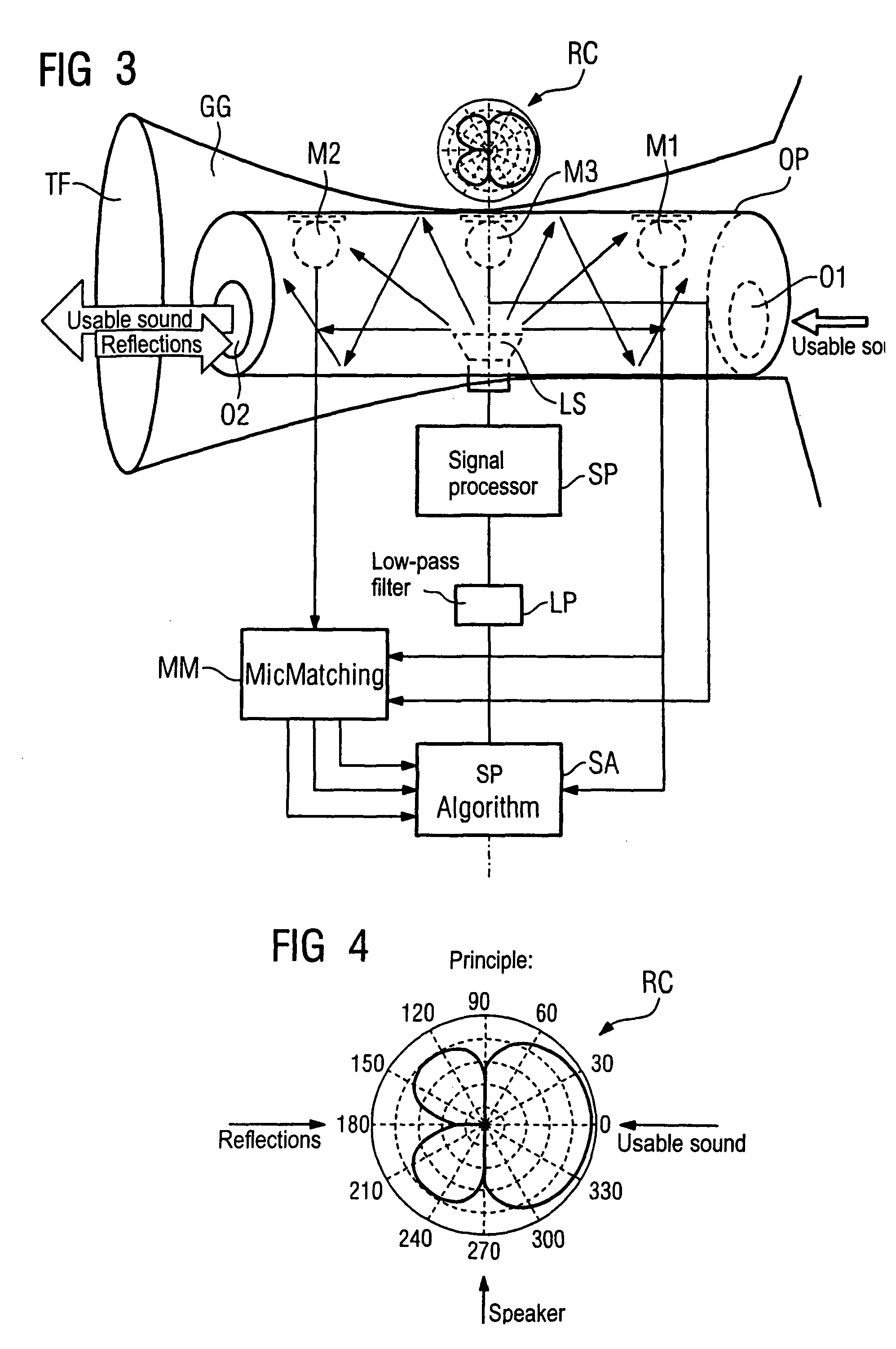
[0025]In a first embodiment according to FIG. 1, the hearing device has a tube-shaped ear fitting piece OP. This ear fitting piece OP has an opening O1 at its exterior-facing side and an opening O2 at its side that faces the inner ear, when inserted in the auditory canal GG. A cylindrical hollow chamber in which a speaker LS is centrally located is fashioned inside the ear fitting piece OP. The primary radiation (emission) direction of the speaker LS is situated perpendicular to the longitudinal axis of the ear fitting piece OP. Two microphones M1 and M2 are arranged inside the ear fitting piece OP acoustically-symmetrically to the speaker LS. “Acoustically-symmetrical” means that the sound from the speaker LS to the microphone M1 is subjected to the same transfer function as the sound from the speaker LS to the microphone M2. Propagation directions of the sound from the speaker LS are indicated by simple arrows in FIG. 1.

[0026]A geometric symmetry line GS is also shown in FIG. 1, t...


PUM


Abstract

In a hearing device with low feedback tendency with simultaneous open feed and utilization of the natural directional effect of the pinna, the hearing device has a tube-shaped ear fitting piece for insertion into an auditory canal and speaker is arranged in the ear fitting piece, and at least two microphones are arranged in the ear fitting piece acoustically-symmetrically to the speaker in the built-in state of the hearing device in the ear fitting piece. The sound emitted by the speaker that can be differentiated from the usable sound, such that the level of feedback can be reduced. At the same time, open feed and utilization of the natural directional effect of the pinna are ensured.

Description

BACKGROUND OF THE INVENTION[0001]1. Field of the Invention[0002]The present invention concerns a hearing device and a method for reduction of feedback therein between a speaker and a number of microphones.[0003]2. Description of the Prior Art[0004]In principle it is desirable to achieve together the following properties of a part of a hearing device located in the ear:[0005]open feed[0006]utilization of the natural directional effect of the pinna (auricle), i.e. microphone position in the auditory canal[0007]freedom from feedback, or at least a low feedback tendency in the system.[0008]The desired properties or requirements cited above are conventionally achieved (each separately) according to the following:[0009]The open feed is achieved with an open ear fitting piece given a behind the ear hearing device (BtE).[0010]The natural directional effect of the pinna can be achieved by a complete CIC device located in the auditory canal, but a ventilation of the auditory canal can be achi...

Claims


Application Information

Patent Timeline
Patent Type & Authority Patents(United States)
IPC IPC(8): H04R25/00
CPCH04R25/407H04R25/453H04R29/006H04R2460/11
Inventor FISCHER, EGHART
Owner SIVANTOS PTE LTD
Learn More