Wind turbine anemometry compensation

a wind turbine and anemometer technology, applied in the field of wind turbine anemometer compensation, can solve the problems that other conventional nacelle wind speed error correction techniques fail to adequately account for the turbulent effect of the blades

Inactive Publication Date: 2011-01-04
GENERAL ELECTRIC CO
View PDF10 Cites 15 Cited by
  • Summary
  • Abstract
  • Description
  • Claims
  • Application Information

AI Technical Summary

Problems solved by technology

However, without the met mast 20, these and other conventional nacelle wind speed error correcting techniques fail to adequately account for the turbulent effects of the blades 10 rotating into and out of the fluid flow path of the anemometer 18 on the nacelle.

Method used


Image

  • Wind turbine anemometry compensation
  • Wind turbine anemometry compensation
  • Wind turbine anemometry compensation

Examples


Embodiment Construction

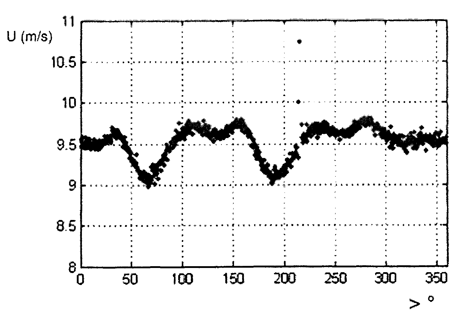
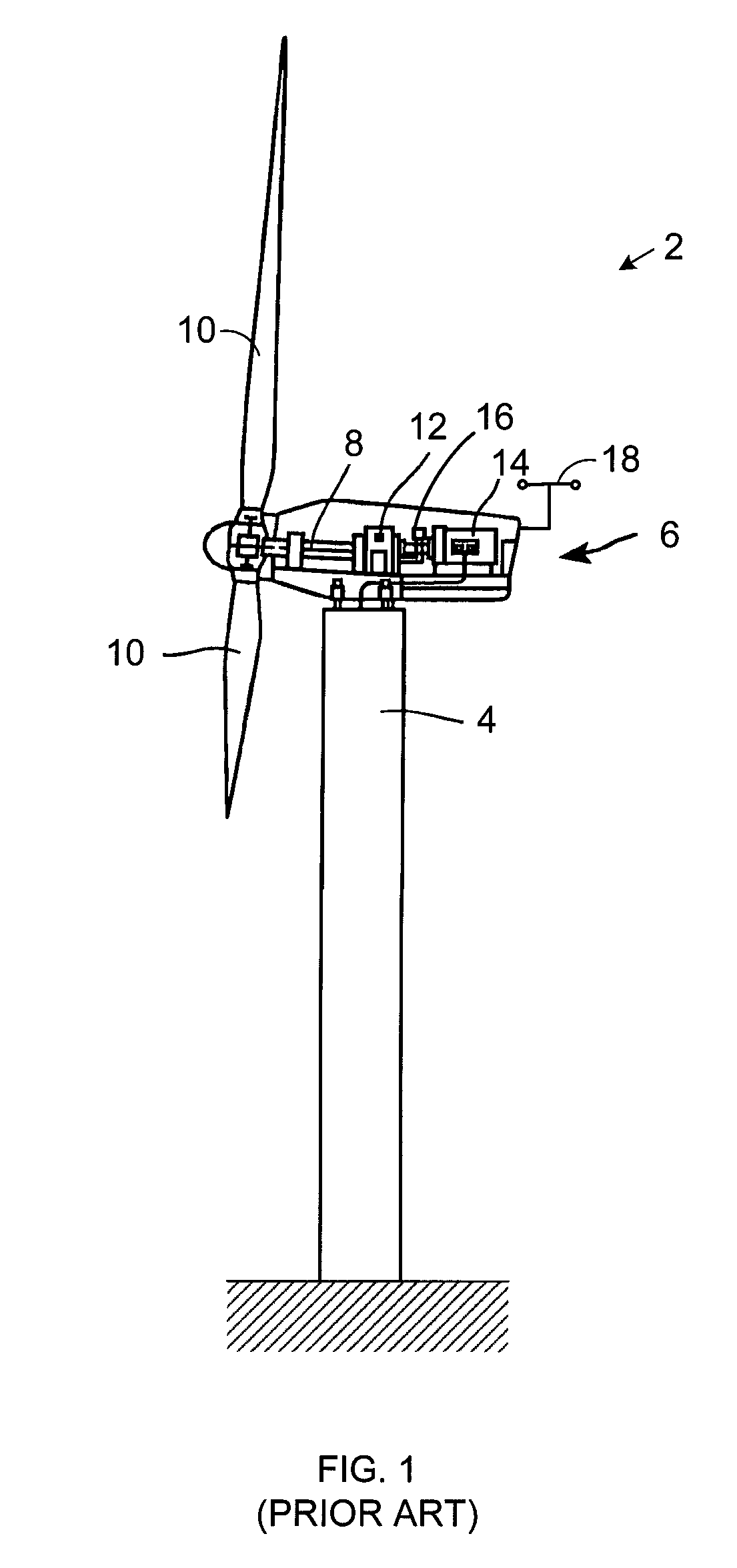
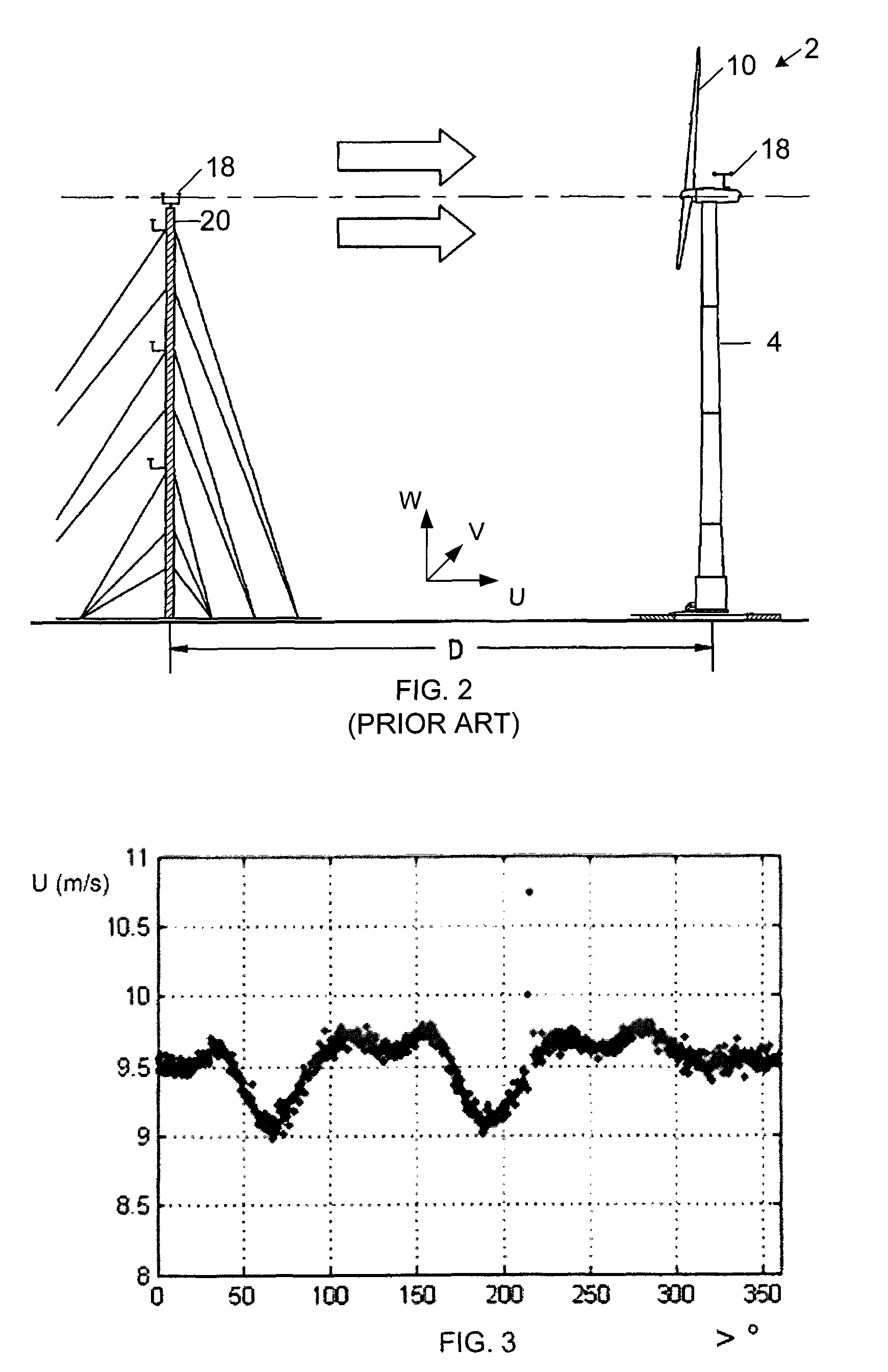
[0026]FIG. 3 is a plot of nacelle wind speed along the rotor axis “U” illustrated inFIG. 2 for average axial wind speeds between nine and ten meters per second. More specifically, the plot shows the nacelle wind speed measured with a three-dimensional, sonic recording anemometer along the axis of the rotor as a function of the angular position of the rotor for measurements falling into a “bin” value of between nine and ten meters per second (“m / s”) along the rotor axis “U” in FIG. 2. However, other anemometers and / or spatial orientations may also be used. FIGS. 4 and 5 show similar plots of average wind speed measurements along the lateral and upward axes, “V” and “W,” identified in FIG. 2 for the same axial wind speed “U” bin of nine to ten m / s. Since the rotor axis “U” may be pitched from horizontal, FIG. 6 further illustrates horizontal wind speed measurements “H” for measured axial wind speeds “U” in the nine to ten m / s bin.

[0027]FIG. 7 is a scatter diagram showing measured hori...


PUM


Abstract

A system for estimating a freestream wind characteristic for a wind turbine having a rotor includes estimating a nacelle wind speed for the turbine; determining, from the estimated nacelle wind speed, at least one angular position of the rotor for measuring a nacelle wind characteristic for the turbine; and measuring the nacelle wind characteristic at the determined angular position of the rotor.

Description

BACKGROUND OF THE INVENTION[0001]1. Technical Field[0002]The subject matter described here generally relates to measuring and testing for rate of flow, and, more particularly, to nacelle-to-freestream compensation of wind speed measurements for wind turbines.[0003]2. Related Art[0004]A wind turbine is a machine for converting the kinetic energy in wind into mechanical energy. If that mechanical energy is used directly by machinery, such as to pump water or to grind wheat, then the wind turbine may be referred to as a windmill. Similarly, if the mechanical energy is further transformed into electrical energy, then the turbine may be referred to as a wind generator or wind power plant.[0005]Wind turbines use one or more airfoils in the form of a “blade” to generate lift and capture momentum from moving air that is them imparted to a rotor. Each blade is typically secured at its “root” end, and then “spans” radially “outboard” to a free, “tip” end. The front, or “leading edge,” of the ...

Claims


Application Information

Patent Timeline
Patent Type & Authority Patents(United States)
IPC IPC(8): G01W1/00
CPCF03D7/02F03D11/0091G01P5/00F05B2260/821F05B2270/32F05B2270/321F05B2270/326F05B2270/404Y02E10/722Y02E10/723F03D17/00Y02E10/72
Inventor HONHOFF, SASKIA G.ROGERS, DONALD M.LANDWEHR, FELIX C.
Owner GENERAL ELECTRIC CO
Why Eureka
Try Eureka