
Voting system and method

Inactive Publication Date: 2011-01-04
STRABONE JEFF
View PDF3 Cites 5 Cited by
  • Summary
  • Abstract
  • Description
  • Claims
  • Application Information

AI Technical Summary

Benefits of technology

The voting apparatus and voting method of the disclosed subject matter are designed to overcome several obstacles, typical of current election practices. Some of these obstacles are perennial difficulties associated with voters' travels to assigned polling places on election day. Others are difficulties that have been brought to public attention in elections of the past decade. The voting apparatus and voting method herein eliminates these obstacles as it produces a more reliable counting of votes cast than current voting systems allow, prevents the fraud that some associate with electronic voting systems, and creates a level of voter confidence in the electoral process that is suitable to a functioning democratic republic.
The voting apparatus and voting method of the disclosed subject matter eliminates the problem of individual machine breakdowns by enabling each voter to use any voting machine at any polling place within the state where he is registered to vote.
The voting apparatus and voting method of the disclosed subject matter allows every registered voter to cast a vote at any polling place in the state where he is registered to vote. Thus, for example, if a voter finds the waiting line to vote too daunting at his home or assigned polling place, the voter is free to travel to another polling place which might have shorter lines and properly working voting machines.
The voting apparatus and voting method of the disclosed subject matter minimizes the number of voters who fail to cast recorded votes due to absentee-related issues. Voters who are far from home on election day but still within the state where they are registered to vote would not need an absentee ballot. Such intrastate-absentee voters could simply vote at any voting machine at any polling place within the state. Only voters who are outside the state (jurisdiction) on election day would need to vote by absentee ballot. Accordingly, the system of the disclosed subject matter reduces the number of voters who need an absentee ballot, and therefore, increases the number of citizens whose votes are cast and recorded, ultimately increasing democratic participation on election day.

Problems solved by technology

Some of these obstacles are perennial difficulties associated with voters' travels to assigned polling places on election day.
Others are difficulties that have been brought to public attention in elections of the past decade.

Method used


Image

  • Voting system and method
  • Voting system and method
  • Voting system and method

Examples


Embodiment Construction

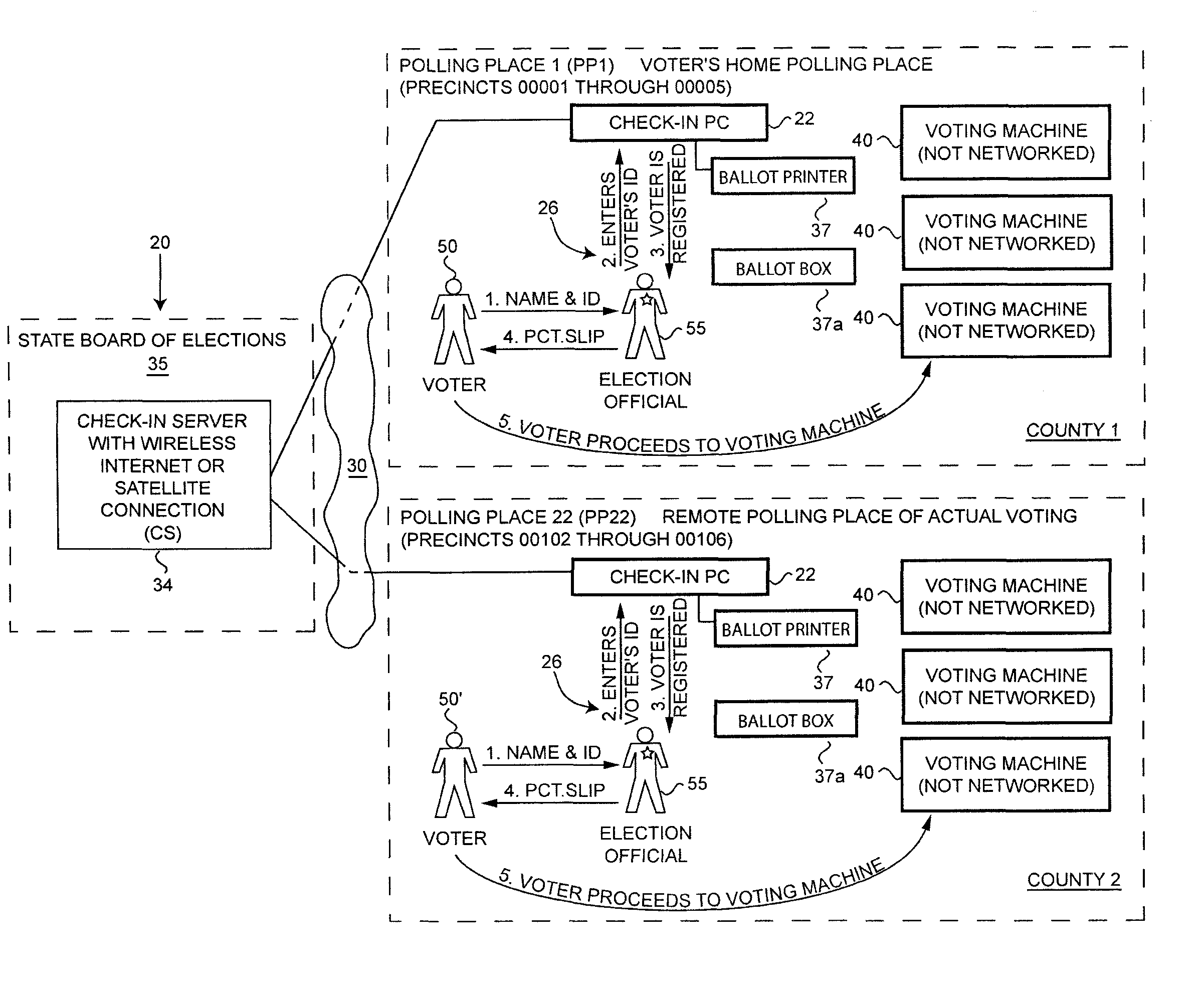
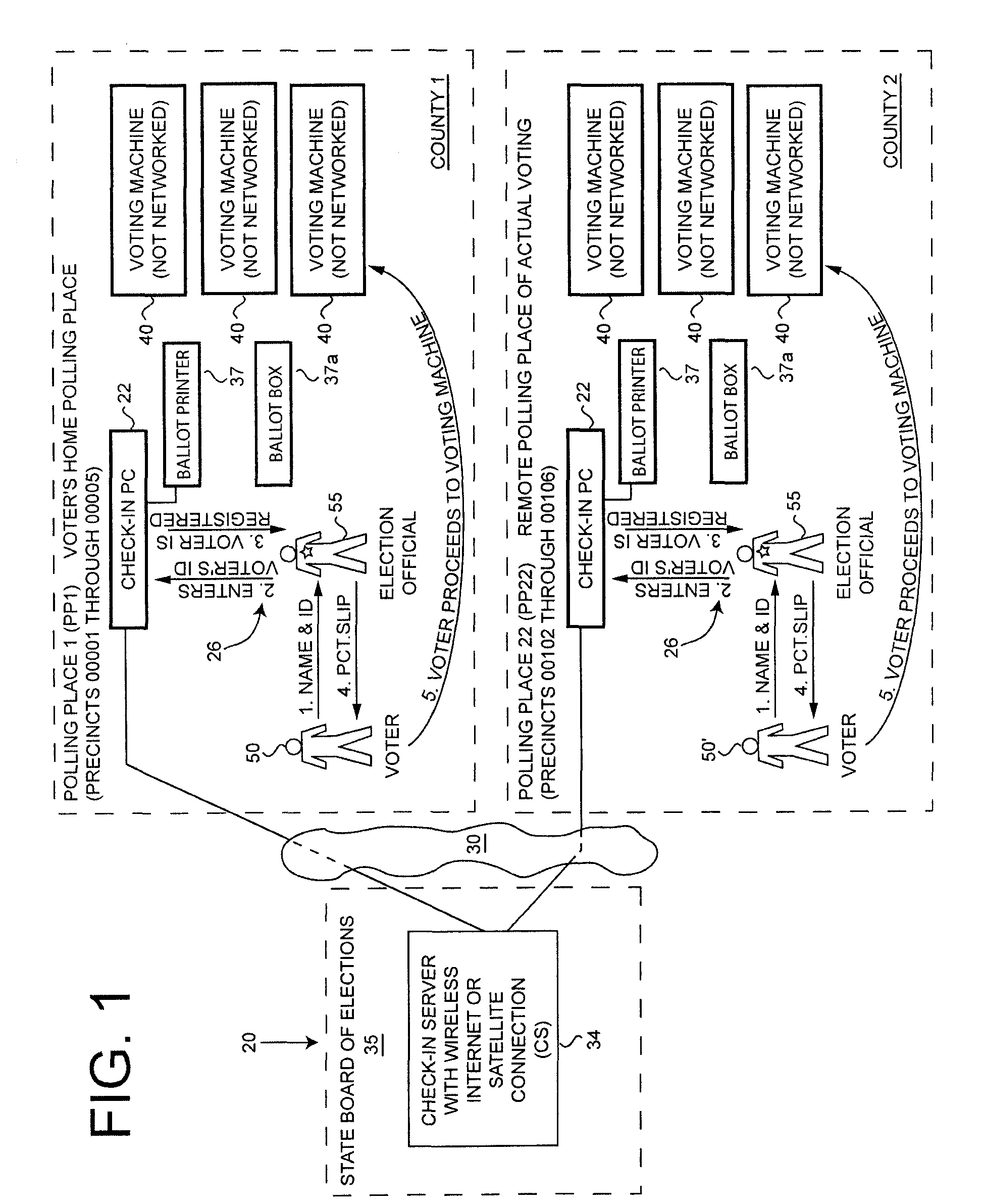
The disclosed subject matter is directed to systems and methods for enabling a voter to vote at any single official polling place in the state (jurisdiction) even if it lies outside the boundaries of his local voting location or area (division of the jurisdiction); and controlling the voting process to prevent fraud, including a single voter voting more than once.

For example, the system shown in the drawing figures and detailed below, to illustrate the disclosed subject matter, is based upon the system presently used in New York State. The system can also be adapted for the jurisdictional divisions of all other U.S. States, Territories, Federal districts and Possessions, as well as foreign nations.

In the exemplary system, as detailed below, New York State is divided into jurisdictional divisions, known generally as “Precincts,”“Voting Precincts,” or “Election Districts (EDs)”, these terms used interchangeably herein. There are presently 16,278 Precincts in the State. New York State ...


PUM


Abstract

Systems and methods are disclosed for enabling a voter to vote at any single official polling place in the state (jurisdiction) even if it lies outside the boundaries of his local voting location (division of the jurisdiction). The systems and methods disclosed also prevent voter fraud, including a single voter voting more than once, at any polling place anywhere in the jurisdiction.

Description

TECHNICAL FIELDThe disclosed subject matter is directed to a method for voting and systems for allowing voters to vote at polling places other than their local assigned polling place, but within the voter's designated jurisdiction, for example, a U.S. State, as well as systems for preventing fraudulent voting.BACKGROUNDThe most widespread difficulty that voters face on election day is getting to their assigned polling places during working hours. It is generally the case in all or almost all of the United States' states, federal districts, territories, and possessions, that on election day each voter must cast his vote in one and only one unique polling place, that is normally assigned to him based on his residence. This requirement can pose insurmountable obstacles to working people, particularly those who work long hours or commute to work.Although a voter might spend his entire day at his workplace, he can only vote at the assigned or “home” polling place nearest his residence, w...

Claims


Application Information

Patent Timeline
IPC IPC(8): G07C13/00G06K17/00H04L9/32G06F11/00
CPCG07C13/00
Inventor STRABONE, JEFF
Owner STRABONE JEFF
Learn More