
Ophthalmic lens element for myopia correction
a technology of ophthalmic lens and myopia correction, applied in the field of ophthalmic lens elements, can solve the problems of conventional myopia correction lenses haphazardly producing clear or defocused images, eye will be unable to properly focus near conventional myopia correction lenses will not be able to properly focus distant objects on the retina, etc., to achieve the effect of improving focussing, correcting, or reducing the progression of myopia
- Summary
- Abstract
- Description
- Claims
- Application Information
AI Technical Summary
Benefits of technology
Problems solved by technology
Method used
Image

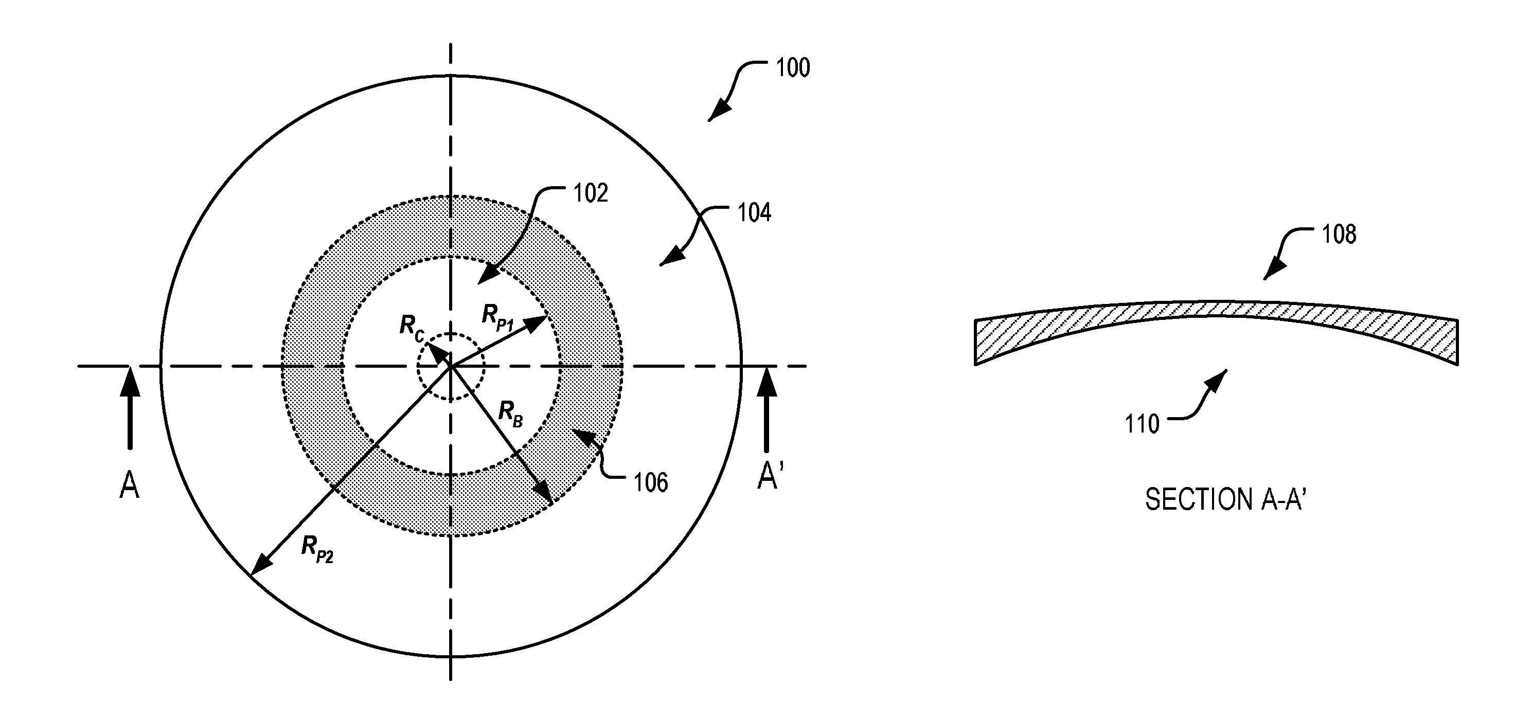
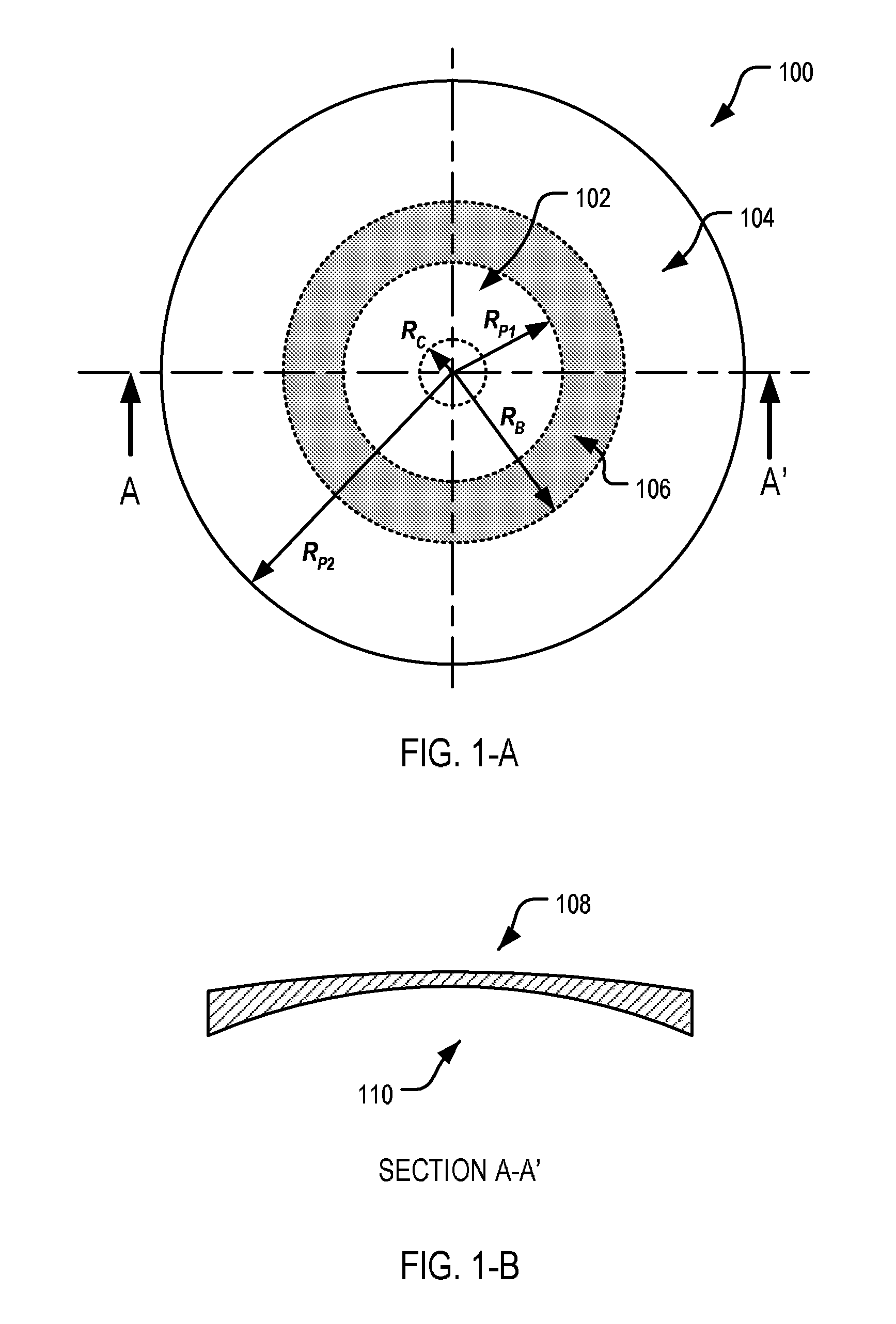
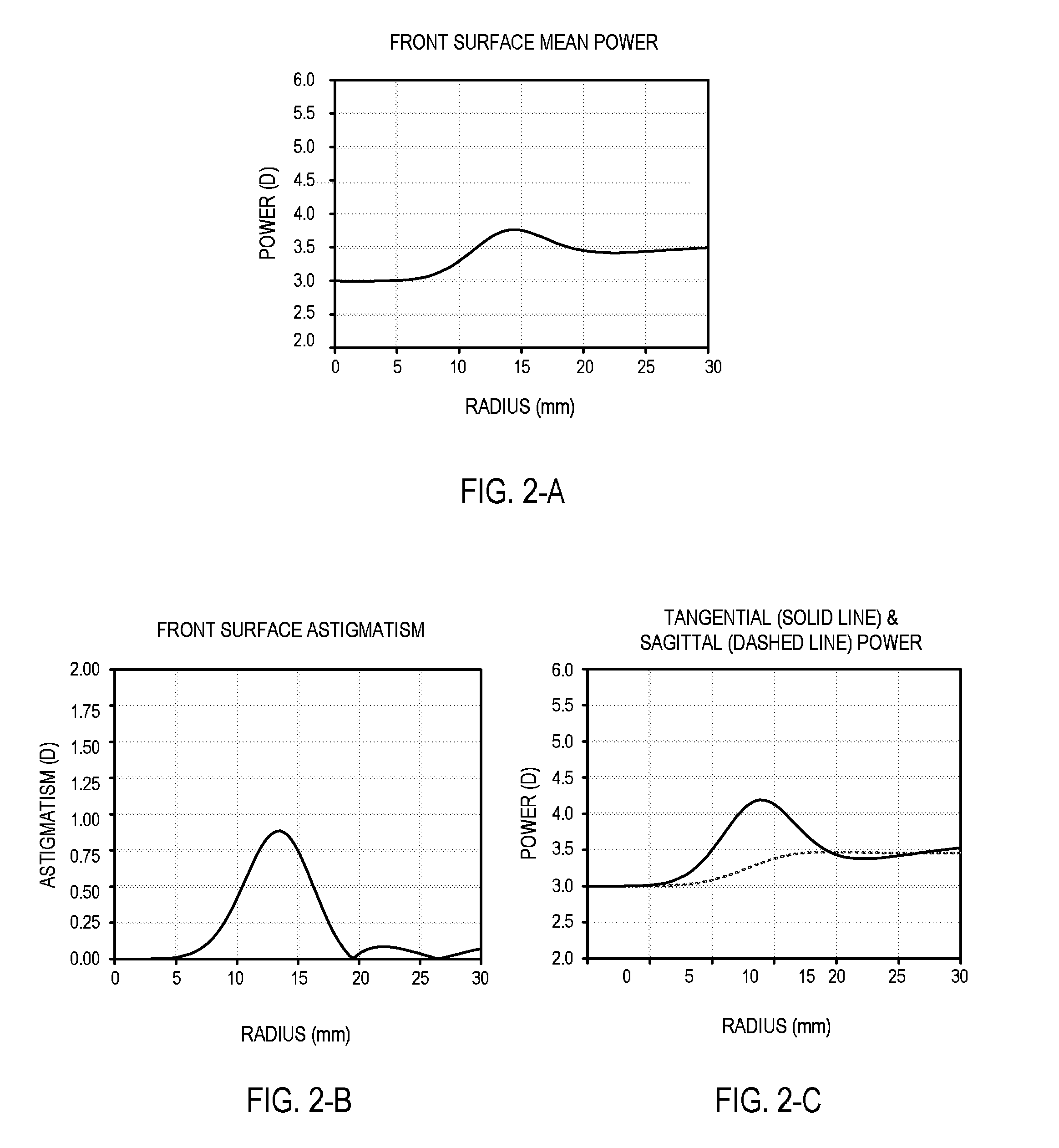
Examples
example 2
[0117]FIG. 3-A illustrates another example of an ophthalmic lens element 200 according to an embodiment of the present invention. In this example, the lens element 200 includes a front surface 108 having the same crown curvature as the lens 100 of Example 1, but a higher mean marginal curvature corresponding to an optical correction of +1.00 D in the peripheral zone relative to the central zone power. The back surface of this lens element 200 and the refracting power of the central zone 102 are the same as per Example 1.
[0118]The front surface 108 uses the same mathematical description as Example 1, with a few parameters changed as listed in table 2.
[0119]
TABLE 2ParameterValueR0176.6 mmR1139.5 mmt0.001m0n0.0000003p5.5a1.0b1.0
[0120]FIG. 4-A to FIG. 4-C show various characteristics of the front surface 108 of the lens 200.
example 3
[0121]FIG. 5-A illustrates an example of an ophthalmic lens element 300 in the 1.6 refractive index material including a front surface 108 having a marginal radius of curvature of 136.5 mm, and the same crown curvature as in Examples 1 and 2 corresponding to an optical correction of around +1.00 D in the peripheral zone 104 relative to the central zone 102 power. That is, in this example, the lens element 300 has a mean crown curvature of 3.40 D, and a mean marginal curvature of 4.39 D at a radius of 20 mm from the lens centre.
[0122]The front surface 108 uses the same mathematical description as Example 1 and Example 2 with a few parameters changed. The revised parameter values are as listed in table 3.
[0123]
TABLE 3ParameterValueR0176.67 mmR1 136.5 mmt0m0n0.0000028p2.5a1.0b1.0
[0124]FIG. 6-A to FIG. 6-C show various characteristics of the front surface 108 of the ophthalmic lens element 300.
[0125]As can be seen from the tangential and sagittal power profiles in FIG. 6-C (and is also ...
example 4
[0127]FIG. 7-A illustrates another example of an ophthalmic lens element 400 according to an embodiment of the present invention. In this example the ophthalmic lens element 400 is manufactured from a 1.6 refractive index material and includes a front surface 108 having the same crown radius as the lens element 300 of Example 3, and a similar marginal curvature in the peripheral zone, corresponding to an optical correction of around +1.00 D in the peripheral zone 104 power relative to the central zone 102 power.
[0128]The lens element 400 has a mean crown curvature of 3.40 D, and a mean marginal curvature of 4.28 D at a radius of 20 mm.
[0129]In this example, unlike the previous examples, the front surface 108 uses a finite element mesh surface mathematical description and has been designed by blending a central spherical surface having a surface power of 3.40 D with a peripheral spherical surface having a surface power of 4.28 D at a radius of 20 mm from the lens centre.
[0130]The ble...
PUM
 Abstract
Description
Claims
Application Information