Stand for oscillating wave-type sprinkler

a technology of oscillating wave and sprinkler, which is applied in the direction of machine supports, other domestic objects, mechanical apparatus, etc., can solve the problems of increasing monetary costs, preventing some areas from receiving adequate water, and insufficient sprinkler elevation alone to produce sprinkler coverage areas, etc., to facilitate easy transportation, setup and relocation, and increase the maximum frame height and sprinkler holder elevation. , the effect of facilitating focused and direct angular adjustmen

Inactive Publication Date: 2011-01-11
GRIFFIN RANDALL
View PDF20 Cites 4 Cited by
  • Summary
  • Abstract
  • Description
  • Claims
  • Application Information

AI Technical Summary

Benefits of technology

[0016]More specifically, the sprinkler stand device of the present invention in an exemplary embodiment, is adapted to accommodate frame extensions to further increase the maximum frame height and sprinkler holder elevation. The movable coupling of the sprinkler holder to the frame also provides a means by which the sprinkler holder may be rotated about the frame in order to vary the direction of the sprinkler. The sprinkler holder may also be rotatively coupled to the frame in a pinwheel type of arrangement to provide further options for adjusting the orientation of the sprinkler.
[0017]The sprinkler stand base may be composed of a plurality of legs arranged to provide stability and support to the frame and holder. In a preferred embodiment, the base is composed of three legs disposed in a tripod arrangement around the frame, facilitating the easy transportation, setup and relocation of the sprinkler stand. In a further embodiment, the base may comprise a stake member adapted for insertion into the ground. The frame may be adjustably coupled to the base, such as swivably attached via a ball-and-socket junction so as to allow both rotative and angular adjustment of the frame orientation and provide for further adjustment of the spray pattern and sprinkler coverage area of an engaged sprinkler, or such as via a ratchet or gear-like arrangement to facilitate focused and direct angular adjustment.

Problems solved by technology

Tall shrubbery, vegetation, or other obstructions in the vicinity of the sprinkler may diminish the sprinkler's efficacy by blocking a portion of the water streams projected from the sprinkler, thereby preventing some areas from receiving an adequate amount of water during the watering session.
In those cases, the delivery of water to undesignated areas during the irrigation process wastes resources, increases the time required to adequately water the designated area due to the volume of water diverted, and results in increased monetary costs.
For a relatively narrow area extending at a distance from the sprinkler, sprinkler elevation alone is insufficient for producing a sprinkler coverage area that more nearly correlates with the size and shape of the targeted lawn area.
Although adequate for their intended purposes, none has taught a sprinkler stand that engages and maintains an oscillating sprinkler in a stable vertical orientation in order to produce a beneficial spray pattern and associated sprinkler coverage area for a narrow designated lawn area.
Although it may be possible to hang an oscillating sprinkler on such a hook, the device is not adapted for nor well-suited for securely maintaining the twin base members of a typical oscillating sprinkler in a desired orientation.
When used with an oscillating sprinkler, such a stand would most likely cause the sprinkler to shake, move, or dislodge in response to the force of the water projected therefrom.
Further, such a device, if used in conjunction with an oscillating sprinkler, would lack disadvantageously angular and rotational adjustability of the sprinkler orientation in order to achieve a desired spray pattern.
However, such stands disadvantageously limit the sprinkler to a horizontal orientation.
Thus, although the elevation of the sprinkler, alone, may prove beneficial, such a pedestal does not provide a means for adjusting the height of the sprinkler; nor is adapted for rotative or angular adjustment of the sprinkler orientation in order to achieve a customized spray pattern for a particular irrigation application.
While adequate for its intended purpose, such an adaptation to a standard oscillating sprinkler does not provide a means by which the spray pattern and sprinkler coverage area of the sprinkler may be uniquely tailored to conform to a particular application; particularly when is required to irrigate a specific region while avoiding watering undesignated areas.
Therefore, none of known devices overcome the limitations previously identified with oscillating sprinklers positioned horizontally on the ground.

Method used


Image

  • Stand for oscillating wave-type sprinkler
  • Stand for oscillating wave-type sprinkler
  • Stand for oscillating wave-type sprinkler

Examples


embodiment 400

[0038]Referring to FIG. 4, a further embodiment 400 of the present invention is depicted. In this embodiment, sprinkler stand base 140 comprises stake member 420. Stake member 420 preferably includes a longitudinal portion with a pointed extremity for insertion into the ground. Stake member 420 may also include extension 424 generally perpendicular to the longitudinal portion and adapted for receiving an applied force, such as foot pressure, when stake member 420 is driven into the ground. Stake member 420 may be composed of wood, metal, PVC, or other substance having sufficient characteristics for frame 130 support and ground insertion.

[0039]The exemplary embodiment 400 depicted in FIG. 4 includes frame extender 430. Frame extender 430 may be coupled to frame 130 and stake member 420 in a telescopic type of arrangement of coupled members of increasing or decreasing diameters. By employing frame extender 430, the height of sprinkler stand 120 may be increased, thereby increasing the...

exemplary embodiment 500

[0044]FIG. 5 depicts an exemplary embodiment 500 of a sprinkler system in which frame 530 is swivelably coupled to base 520, shown as a stake, by socket coupler 525. Socket coupler 525 is cylindrically shaped and adapted to receive the lower end portion of frame 530. Frame 530 has a rounded lower end portion resembling a ball that is adapted for coupling with socket coupler 525 to form a ball-and-socket junction. The ball-and-socket junction of frame 530 and base 520 allows frame 530 to swivel so that both rotational and angular adjustments may be made to modify frame 530 orientation and thus optimize water delivery to a designated area. Frame 530 may be swiveled to tailor the sprinkler coverage area to the size and shape of the lawn area to be watered. By tailoring the sprinkler coverage area to the designated area to be watered, less water is wasted on unintended areas, thereby reducing the amount of water consumed during the watering process. Because more of the water supplied to...

embodiment 800

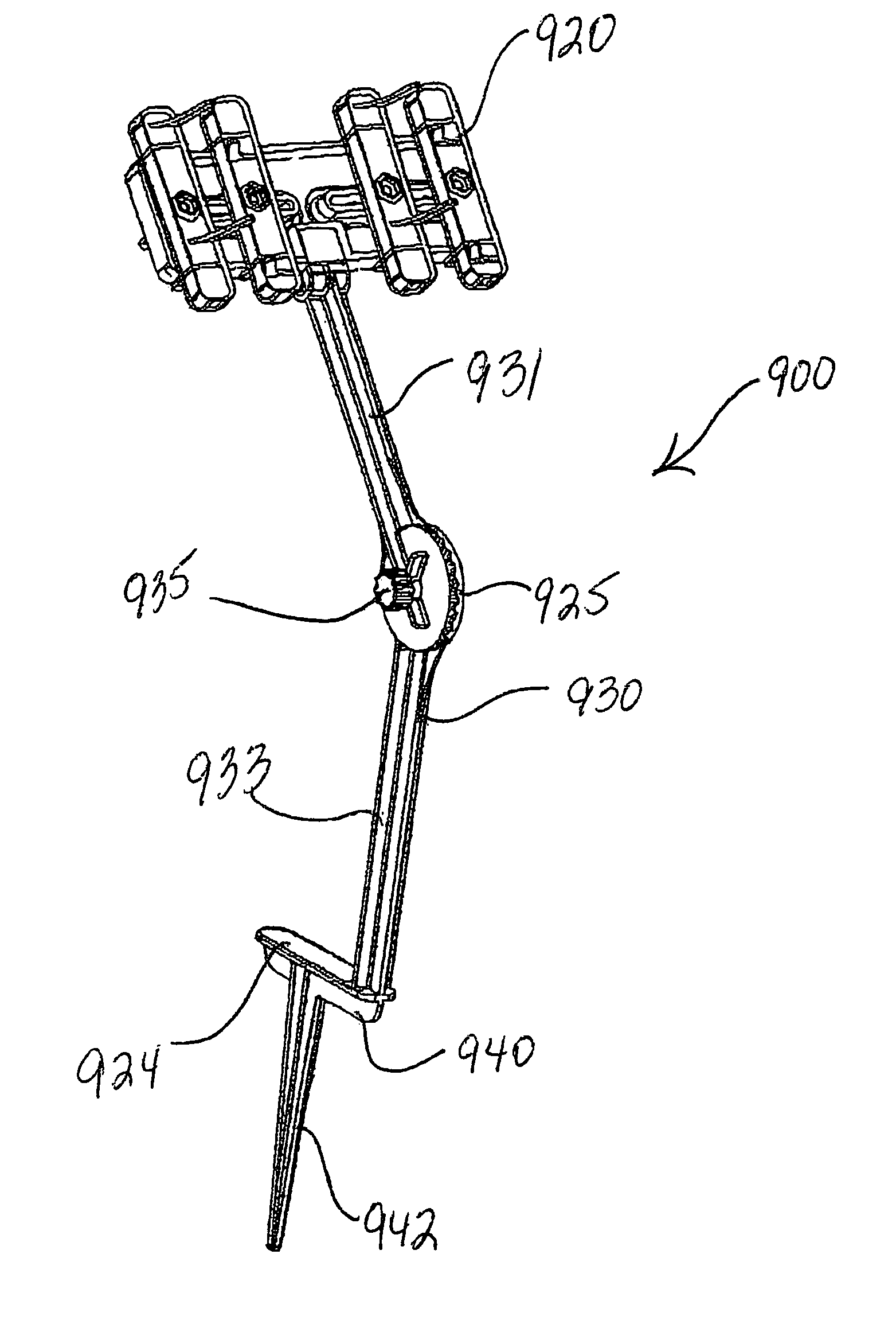
[0055]In embodiment 800 of a sprinkler system, upper arm 831 and lower arm 833 are swivelably coupled by ball-socket coupler 825. Ball-socket coupler 825 is generally spherically-shaped and adapted to connect upper arm 831 and lower arm 833 in a manner that facilitates maximum adjustability within a variety of planes. Upper arm 831 has a rounded lower end portion resembling a ball that is adapted for coupling with female socket to define the junction at ball-socket coupler 825. The ball-and-socket junction at ball-socket coupler 825 allows frame 830 to swivel so that both rotational and angular adjustments may be made to modify orientation and thus optimize water delivery to a designated area. Frame 830 may be swiveled to tailor the sprinkler coverage area to the size and shape of the lawn area to be watered. By tailoring the sprinkler coverage area to the designated area to be watered, less water is wasted on unintended areas, thereby reducing the amount of water consumed during th...


PUM


Abstract

A sprinkler stand for holding an oscillating sprinkler in an elevated and generally vertical orientation to provide a desired sprinkler coverage pattern, wherein a sprinkler holder holds a sprinkler, a frame elevates and supports the sprinkler holder, and a base supports the frame. Preferably, the sprinkler holder includes two tracks for engaging base members of a sprinkler, wherein the tracks allow for the repositioning of the sprinkler so as to vary the sprinkler elevation, the height of the sprinkler holder is adjustable by moving the holder along the frame, or by adding a frame extender to the frame, and the sprinkler holder may be rotated, or the frame rotatably or angularly adjusted to achieve a desired sprinkler orientation.

Description

CROSS-REFERENCE TO RELATED APPLICATION[0001]This application claims priority to and the benefit of, and is a Continuation-in-Part of U.S. Utility patent application Ser. No. 11 / 222,467, filed Sep. 8, 2005, now U.S. Pat. No. 7,708,210, entitled “Stand for Oscillating Wave-Type Sprinkler”.FIELD OF THE INVENTION[0002]This invention relates in general to stands for watering devices. In particular, this invention relates to a stand for an oscillating tube water sprinkler that both elevates the sprinkler and maintains it in a generally vertical position.BACKGROUND OF INVENTION[0003]Oscillating water sprinklers are well known and their use constitutes a popular method of watering a lawn or garden. Typically, an oscillating water sprinkler includes a base formed by two generally straight and opposing parallel members that join two generally curved opposing end portions. A perforated spray tube, which receives and projects water, is coupled to and supported by the base. Water may be supplied...

Claims


Application Information

Patent Timeline
Patent Type & Authority Patents(United States)
IPC IPC(8): A01G25/09B05B17/00
CPCB05B3/044B05B15/062B05B15/063A62C31/24B05B15/066B05B15/067B05B3/14B05B15/622B05B15/625B05B15/652B05B15/654
Inventor GRIFFIN, RANDALL
Owner GRIFFIN RANDALL
Why Eureka
Try Eureka