Nanoscale moiety placement methods

a nanoscale moiety and placement method technology, applied in the field of nanotechnology, can solve the problems of deterministic placement of nanoscale moieties in incompatible means with the use of pre-made photolithographic masks (photomasks) to fabricate additional features, and inability to place hundreds, thousands, millions or more nanotubes on one substrate at sparsely packed deterministic sites consistent with fixed photomask patterns used for many electrode fabrication

Active Publication Date: 2011-01-11
AGILENT TECH INC
View PDF3 Cites 61 Cited by
  • Summary
  • Abstract
  • Description
  • Claims
  • Application Information

AI Technical Summary

Problems solved by technology

A general problem in nanotechnology is the siting of nanoscale moieties (nanomoieties) in sparsely packed deterministically located sites on a substrate surface.
This difficulty arises because the sizes of nanomoieties such as nanotubes, nanowires, nanorods, nanofibers, quantum dots, and nanoscale seed particles (nanoseeds) can be on the order of 1-10 nm, smaller than the size of the smallest site that can be created at a predetermined location by an available method comprising one of scanning probe lithography, dip pen nanolithography, electron beam lithography, focused ion beam lithography, X-ray lithography, photolithography, and the like.
Additionally, such means are incompatible with the use of pre-made photolithographic masks (photomasks) to fabricate additional features, either before or after, on the same substrate at predetermined locations with are far apart compared to the size of an individual nanomoiety.
However, the placement of hundreds, thousands, millions, or more of nanotubes on one substrate at sparsely packed deterministic sites consistent with fixed photomask patterns used for fabrication of many electrodes is problematic.
The placement of multiple such elements is often problematic.

Method used


Image

  • Nanoscale moiety placement methods
  • Nanoscale moiety placement methods
  • Nanoscale moiety placement methods

Examples


first embodiment

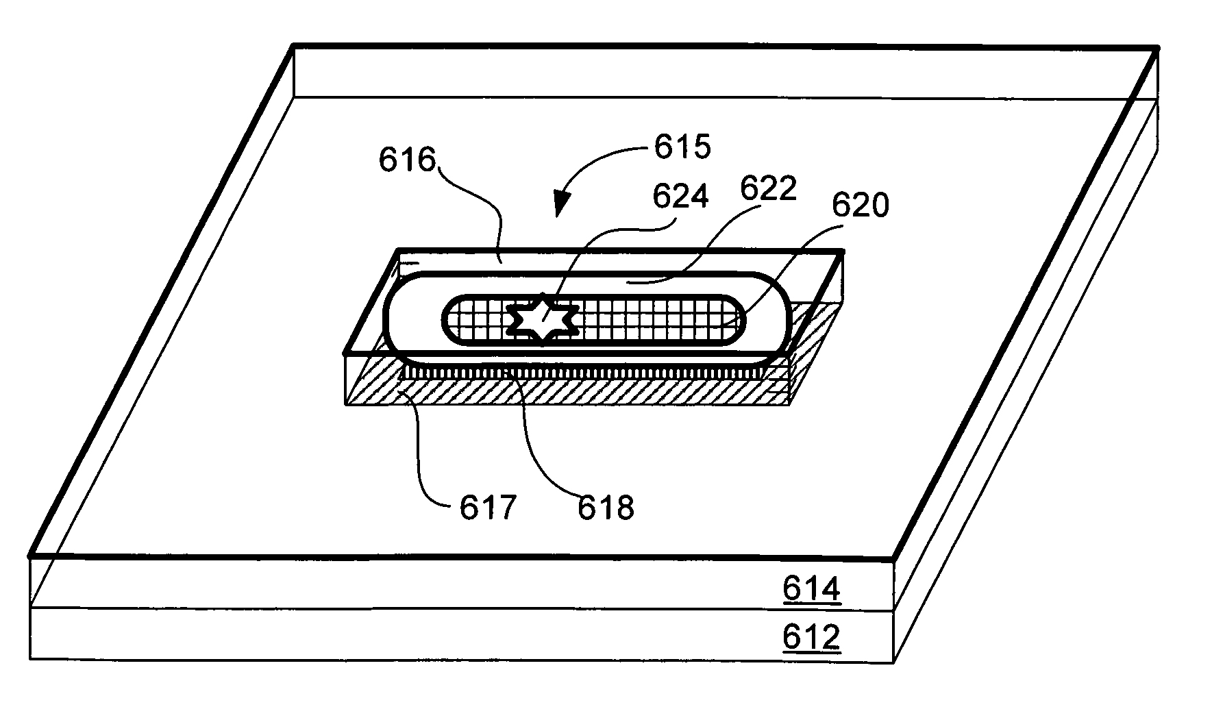
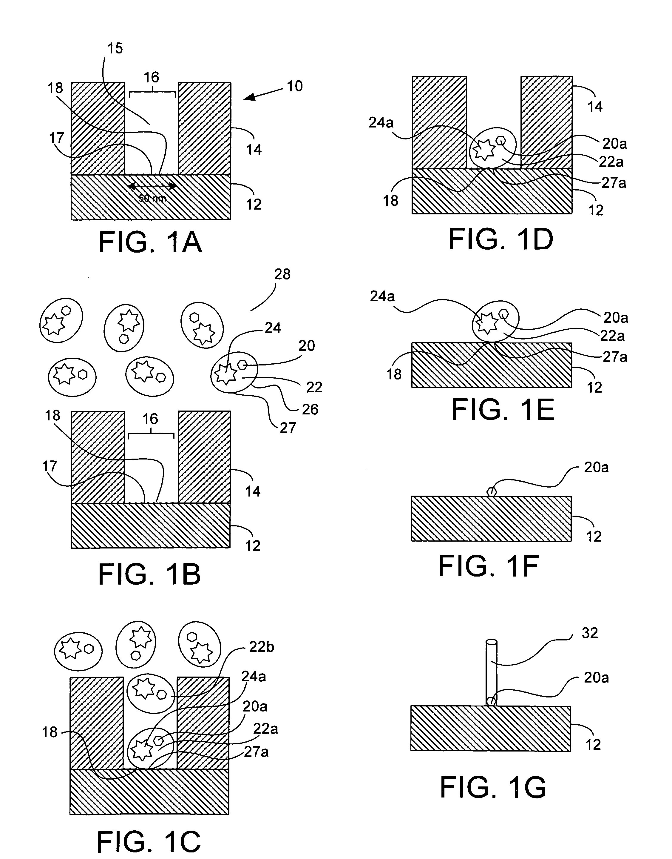
In the method, a structure having a location layer (e.g., about 200 nm thick) is disposed atop a substrate. The location layer has a location feature (e.g., a nanoscale hole or pit of about 50 nm in diameter and extending through the thickness of the location layer) being at a deterministic location defined by known methods, for example electron beam lithography. The exposed portion of the substrate at the bottom of the location feature includes a binding patch having a binding characteristic.

The structure is introduced to a delivery medium including a solution having a nanoscale delivery vehicle. The delivery vehicle is coupled to a nanomoiety, for example a seed particle, and has a binding region on all or a portion of its exposed surface. The nanomoiety and the delivery vehicle may be a unitary system wherein the nanomoiety may exist in potential only, comprising a part of the delivery vehicle to be rendered from the delivery vehicle by a subsequent process such as, but not limit...

second embodiment

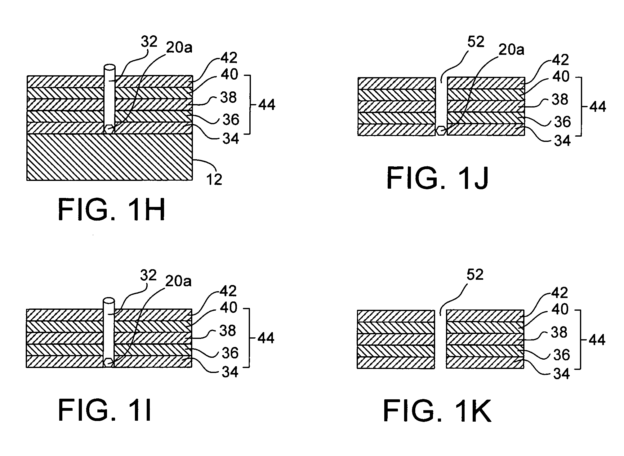
In a second embodiment, a nanomoiety is both placed at a deterministic location and is placed in a well-defined orientation, for example, perpendicular to the top surface of the substrate. The method includes providing a structure having a location layer, for example about 200 nm thick, disposed on a substrate, where the location layer has a location and alignment feature. For example, the location and alignment feature can include, but is not limited to, a nanoscale hole, about 50 nm in diameter with substantially vertical walls and extending through the thickness of the alignment layer. The exposed portion of the substrate at the bottom of the hole includes a binding patch having a binding characteristic.

Then, the structure is introduced to a delivery medium including a solution having a nanoscale delivery vehicle, wherein the nanoscale delivery vehicle is associated to the nanomoiety to be placed, and the nanoscale delivery vehicle has a binding region. The nanomoiety may be, for...


PUM

PropertyMeasurementUnit
sizesaaaaaaaaaa
diametersaaaaaaaaaa
diameteraaaaaaaaaa

Abstract

Methods and structures for placing nanoscale moieties on substrates are provided.

Description

BACKGROUNDA general problem in nanotechnology is the siting of nanoscale moieties (nanomoieties) in sparsely packed deterministically located sites on a substrate surface. This difficulty arises because the sizes of nanomoieties such as nanotubes, nanowires, nanorods, nanofibers, quantum dots, and nanoscale seed particles (nanoseeds) can be on the order of 1-10 nm, smaller than the size of the smallest site that can be created at a predetermined location by an available method comprising one of scanning probe lithography, dip pen nanolithography, electron beam lithography, focused ion beam lithography, X-ray lithography, photolithography, and the like.Several means have been developed to provide stochastically located, densely packed arrays of nanomoieties on a substrate, among which is the use of diblock copolymers. These means typically result in a structure with some local order, comprising for example a hexagonal close-packed array of nanomoieties on a planar surface, but the pa...

Claims


Application Information

Patent Timeline
Patent Type & Authority Patents(United States)
IPC IPC(8): G01N33/543
CPCG01N33/54353
Inventor BARTH, PHILLIP W.
Owner AGILENT TECH INC
Why Eureka
Try Eureka