Method and apparatus for high efficiency rectification for various loads

a technology of load rectification and load, applied in the direction of circuit arrangement, dc source parallel operation, impedence matching network, etc., can solve the problem of reducing the overall conversion efficiency of the circuit, affecting the load seen by the transmitter, and rarely achieving the optimum power transfer between the external device and the implant device, etc. problem, to achieve the effect of optimal conversion efficiency

Active Publication Date: 2011-01-11
POWERCAST
View PDF16 Cites 404 Cited by
  • Summary
  • Abstract
  • Description
  • Claims
  • Application Information

AI Technical Summary

Problems solved by technology

However, variations in either the input power or load impedance degrade the overall conversion efficiency of the circuit.
As a result, optimum power transfer between the external device and implant device is rarely achieved.
The problem presented is that the load seen by the transmitter changes depending on the status of the plasma in the chamber.

Method used


Image

  • Method and apparatus for high efficiency rectification for various loads
  • Method and apparatus for high efficiency rectification for various loads
  • Method and apparatus for high efficiency rectification for various loads

Examples


first embodiment

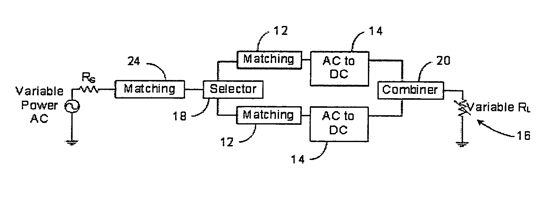
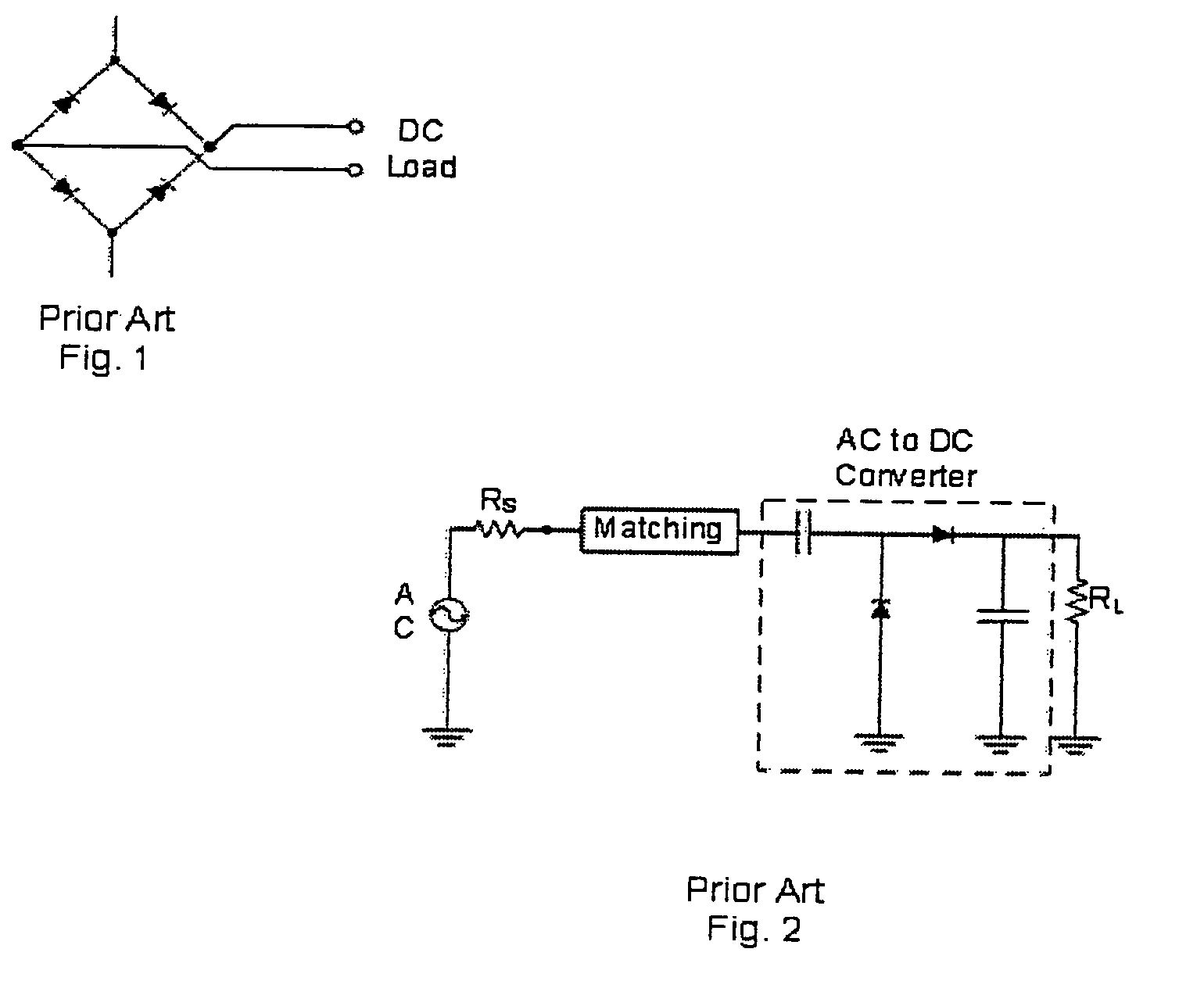
[0120]The present invention can be implemented for a number of different combinations. In a first embodiment, the load 16 is fixed at or near the optimal load 16 resistance, which was described above, and the input power is variable. As stated previously, with proper design the AC to DC converter 14 in FIG. 2 can efficiently drive a fixed load 16 over a limited input power range. This can be seen in FIG. 5. However, if it is desired to efficiently drive the load 16 over a larger input power range than can be provided by the prior art or if it is found to be advantageous in other applications where the load 16 is fixed, the invention can be used. A block diagram of an embodiment of the invention can be seen in FIG. 9, where the AC to DC converter includes a selector, two first impedance matching networks 12, two AC to DC converters 14, and a combiner 20 in communication with an input and a load 16.

[0121]As shown in FIG. 9, the input is an AC source with a source impedance, RS, which ...

second embodiment

[0126]A second embodiment for how the invention can be implemented is to have a fixed input power and a variable load 16 resistance, which is shown in FIG. 11.

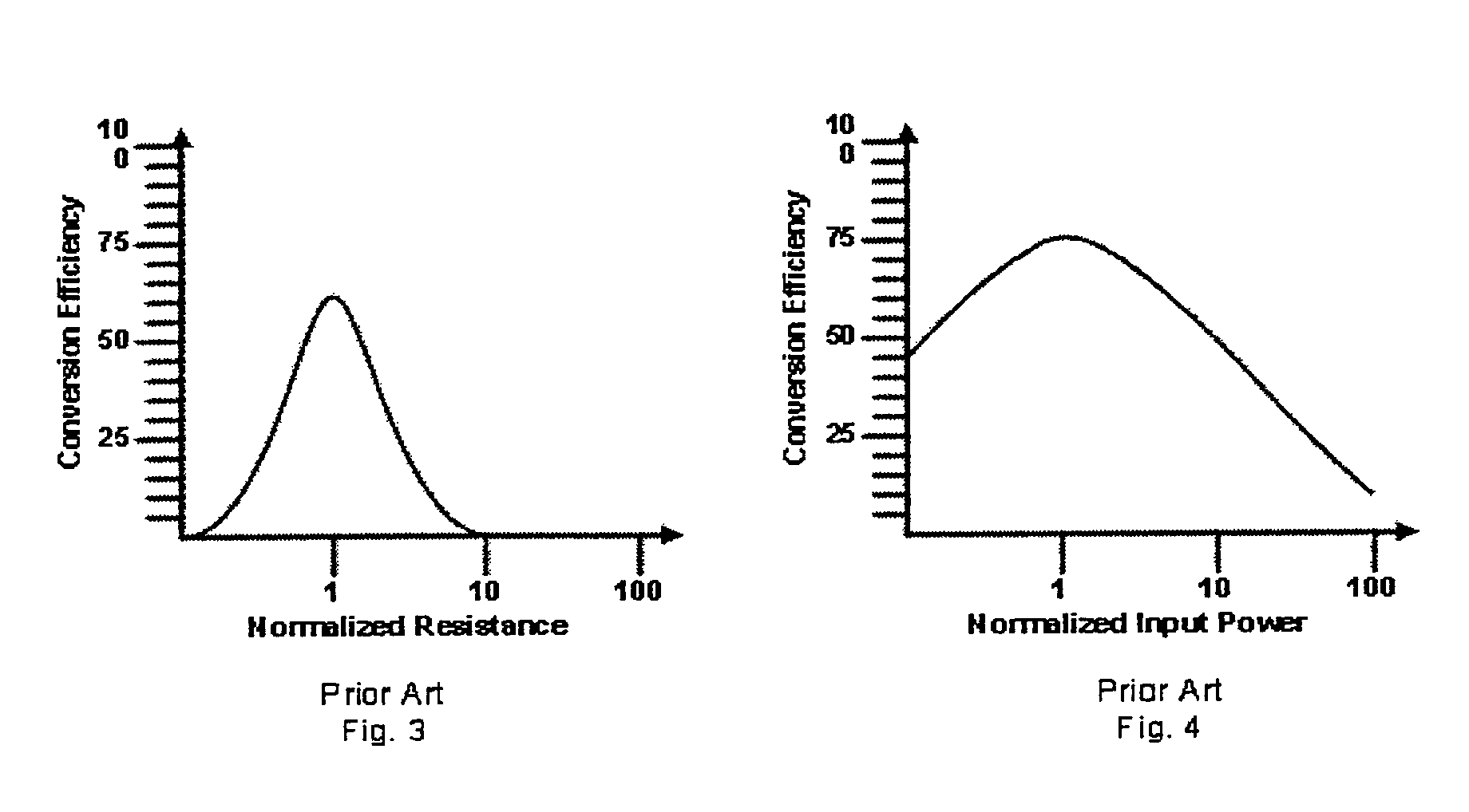
[0127]In the prior art circuit in FIG. 2, there will be loss described by the Maximum Power Transfer Theorem due to the mismatch of the AC to DC converter 14 output resistance and the load 16 resistance. The corresponding conversion efficiency will be similar to that shown in FIG. 3. The AC to DC converter 14 in FIG. 2 can be matched to loads 16 other than the optimal load 16 resistance to minimize the loss in conversion efficiency caused by input mismatch at that load 16 resistance value. However, there will still be loss in conversion efficiency due to the mismatch between the AC to DC converter 14 output DC resistance and the load 16 resistance and the conversion efficiency will take a shape similar to that shown in FIG. 3. There will also be loss due to impedance mismatch between the impedance of the input and the input of...


PUM


Abstract

An apparatus for converting power includes at least one impedance matching network which receives an electrical signal. The apparatus includes at least one AC to DC converter in communication with the impedance matching network. Also disclosed is a method for powering a load and an apparatus for converting power and additional embodiments of an apparatus for converting power.

Description

CROSS-REFERENCE TO RELATED APPLICATIONS[0001]This application claims the benefit of U.S. Provisional Patent Application Ser. No. 60 / 729,792, filed Oct. 24, 2005.BACKGROUND OF THE INVENTION[0002]1. Field of the Invention[0003]The present invention is related to a method and apparatus for converting power. More specifically, the present invention is related to a method and apparatus for converting power with an AC to DC converter.[0004]2. Description of Related Art[0005]The prior art has shown that it is possible to provide power to remote devices using Radio-Frequency (RF) electromagnetic waves. Wireless power transfer has been described in great detail by W. C. Brown in U.S. Pat. No. 3,114,517, “Microwave Operated Space Vehicles,” incorporated by reference herein, and within numerous other articles by the stated author. Wireless power transfer is also used to provide power to Radio-Frequency Identification (RFID) tags. The transmitted RF power is captured by an antenna and rectified...

Claims


Application Information

Patent Timeline
Patent Type & Authority Patents(United States)
IPC IPC(8): H02J5/00H05B44/00
CPCH02J1/10H02M7/103H02M7/08H02J7/32H02J50/20H05B45/37H02J50/001H02M7/04H02M7/162H04M1/00H01Q11/12H04B1/38H02M3/04H03H11/28
Inventor GREENE, CHARLES E.HARRIST, DANIEL W.
Owner POWERCAST
Why Eureka
Try Eureka